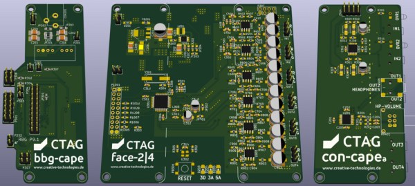
Swapping GPIO Pins On The Pi Zero For Audio

The new Raspberry Pi Zero is generating a lot of discussion, especially along the lines of “why didn’t they include…?” One specific complaint has been that audio is only available through the HDMI port. That’s not entirely true as pointed out by Lady Ada over at Adafruit.

Something to remember about the entire Pi family is the pins on the Broadcom processors are multipurpose. Does it increase the confusion or the capabilities? Take your pick. But the key benefit is that different pins can handle the same purpose. For audio the Greater Than Zero Pis (GTZPi) use PWM0_OUT and PWM1_OUT on the processor’s GPIO pins 40 and 45. On the GRZPis these feed a diode, resistor and capacitor network that ends at the audio output jack. They don’t appear on the GPIO connector so cannot be used on the Zero.

The multi-pin, multi-purpose capability of the Broadcom processor allows you to switch PWM0_OUT to GPIO 18 and PWM1_OUT to GPIO 13 or 19. Add the network from the Adafruit note, or check this schematic from the Raspberry Pi site – look at the lower right on the second page.

raspberry_pi_audiofilter

While you’re checking out the audio hack at Adafruit, read through the entirety of Introducing the Raspberry Pi Zero. Lady Ada provides a great description of the Zero and what is needed to start using it.

If you’re looking for Zero hacking ideas you might check the comments in our announcement about the Zero or article on the first hack we received. There is a lot of grist for the hacking mill in them.

Audio Effects On The Intel Edison

With the ability to run a full Linux operating system, the Intel Edison board has more than enough computing power for real-time digital audio processing. [Navin] used the Atom based module to build Effecter: a digital effects processor.

Effecter is written in C, and makes use of two libraries. The MRAA library from Intel provides an API for accessing the I/O ports on the Edison module. PortAudio is the library used for capturing and playing back audio samples.

F9GW4Y4IGQFYP23.MEDIUMTo allow for audio input and output, a sound card is needed. A cheap USB sound card takes care of this, since the Edison does not have built-in hardware for audio. The Edison itself is mounted on the Edison Arduino Breakout Board, and combined with a Grove shield from Seeed. Using the Grove system, a button, potentiometer, and LCD were added for control.

The code is available on Github, and is pretty easy to follow. PortAudio calls the audioCallback function in effecter.cc when it needs samples to play. This function takes samples from the input buffer, runs them through an effect’s function, and spits the resulting samples into the output buffer. All of the effect code can be found in the ‘effects’ folder.

You can check out a demo Effecter applying effects to a keyboard after the break. If you want to build your own, an Instructable gives all the steps.

Continue reading “Audio Effects On The Intel Edison”

Video From Audio And Pure Data

Although graphical programming languages have been around for ages, they haven’t really seen much use outside of an educational setting. One of the few counterexamples of this is Pure Data, and Max MSP, visual programming languages that make music and video development as easy as dropping a few boxes down and drawing lines between them.

A few years ago, [Thomas] and [Danny] developed a very cool Pure Data audio-visual presentation. The program they developed only generated graphics, but though clever coding they were able to generate a few audio signals from whatever video was coming out of their computer. The project is called TVestroy, and it’s one of the coolest audio-visual presentations you’ll ever see.

The entire program is presented on three large screens and nine CRT televisions. With some extremely clever code and a black box of electronics, the video becomes the audio. Check it out below.

Although this is a relatively old build, [Thomas] thought it would be a good idea to revisit the project now. He’s open sourced most of the Pure Data files, and everything can be downloaded on the project page.

Continue reading “Video From Audio And Pure Data”

Tape Loop Echo Made With An Actual Tape Loop

A lot of digital processes are named after an old analog device that they’ve since replaced. It’s not uncommon to “tape” a show nowadays, for example, even though the recording work is actually done by a digital video recorder. Sometimes, though, the old analog devices have a certain je ne sais quoi that is desirable even in today’s digital world. This is certainly the case with [Dima]’s tape loop echo which is actually made with a physical tape loop.

The process of building the tape loop hardware is surprisingly non-technical. By positioning a recording head and a playback head right next to one another, a delay is introduced. An echo is created by mixing the original live sound signal with this delayed signal coming from the tape By varying the speed of the tape or altering several other variables, many different-sounding effects can be achieved.

Although in practice it’s not as simple as it sounds (the device required a lot of trial-and-error), the resulting effect is one that Pink Floyd or Beck would surely be proud of. Analog isn’t the only way to go though, there are plenty of digital effects that are easily created, and some with interesting mounting options as well.

Continue reading “Tape Loop Echo Made With An Actual Tape Loop”

The Kraakdoos — Musical Abuser Of An Ancient OpAmp

A friend from the newly founded Yeovil Hackerspace introduced me to a device known as “The Kraakdoos” or cracklebox.

The cracklebox is an early electronic instrument produced by STEIM in the 1970s. The instrument consists of a single PCB with a number of copper pads exposed on one side. The player touches the pads and the instrument emits… sounds which can perhaps best be described as squeeze and squeals.

While the cracklebox was original sold as a complete instrument, the device has been reverse engineered, and the schematic documented. What lies inside is quite fascinating.

The heart of the cracklebox is an ancient opamp, the LM709. The LM709 is the predecessor to the famous LM741. Unlike the 741 the 709 had no internal frequency compensation. Frequency compensation is used to intentionally limit the bandwidth of an opamp. As input frequency increases, the phase shift of the opamp also increases. This can result in undesirable oscillation, as the feedback network forms an unintentional phase-shift oscillator.

Most modern opamps have internal frequency compensation, but the 709 doesn’t. Let’s see how this is used in the cracklebox:

krackdoos_schRather than using the frequency compensation pins as intended the cracklebox just routes them out to pads. In fact the cracklebox routes almost all the pins on the opamp out to pads, including the inverting and non-inverting inputs. A single 1MOhm feedback resistor is used in a non-inverting configuration. However reports suggest the instrument can work without a feedback resistor at all!

Continue reading “The Kraakdoos — Musical Abuser Of An Ancient OpAmp”

Laser Cut Your Own Vinyl Records

[Amanda Ghassaei] has created an awesome hack for making your own vinyl records using a laser cutter from an MP3 file. Her excellent hack uses a Processing sketch that converts a digital audio file into a vector graphics file, which is then burned onto vinyl using a laser cutter. We saw a demo of this at the FabLab11 conference, and it’s an impressive hack.

One of the best parts of her write up are the details of how she arrived at the appropriate processing settings to get the record sounding as good as possible, but still be cuttable. It’s an object lesson in how you iterate on a project, trying different approaches and settings until you find the one that works. She also decided to take it a few steps further, cutting records on paper and wood for the ultimate eco-friendly record collection.

Audiophiles should avoid this technique though. Due to limitations in the resolution of the laser cutter, [Amanda] ended up having to reduce the bandwidth of the audio signal to 4.5Khz and use a 5-bit sampling depth. That translates to a rather tinny-sounding record. Vinyl record snobs can breathe easy: this isn’t going to replace their beloved white-hot stampers. For the rest of us, there are always records etched into tortillas.

Continue reading “Laser Cut Your Own Vinyl Records”

Hackaday Prize Entry: Superb Audio With The Teensy

The Raspberry Pi and Teensy 3 both have I2S interfaces, and that means these boards can be used to play very high quality audio. A codec and an I2S interface is one thing, but turning that digital stream into a quality analog output is another thing entirely. You need only look at audiophile forums for enough mis- and disinformation for that evidence.

For his Hackaday Prize entry [William Hollender] is building an audio board for the Teensy 3.x. It features very high-end opamps, the right filters, and the correct topology to turn a digital audio stream into an analog signal that would please the most temperamental ear.

The Teensy Super Audio Board uses the Cirrus CS4272 audio codec chip, a high quality chip that can handle sample rates of up to 192kHz at 24 bit depth. This chip doesn’t include the analog input and output buffers, and this means [William] has quite a build in front of him. This means using high quality opamps, low noise power supplies, and knowing how to build a circuit and measure its noise.

So far, the tests revealed incredible dynamic range, flatness, and frequency response of this tiny little board. It also works with the Raspberry Pi. Now it’s just a matter of getting a few more of these boards put together for the Best Product part of the Hackaday Prize.


The 2015 Hackaday Prize is sponsored by: