Amazing Open Source Quadruped Capable Of Dynamic Motion

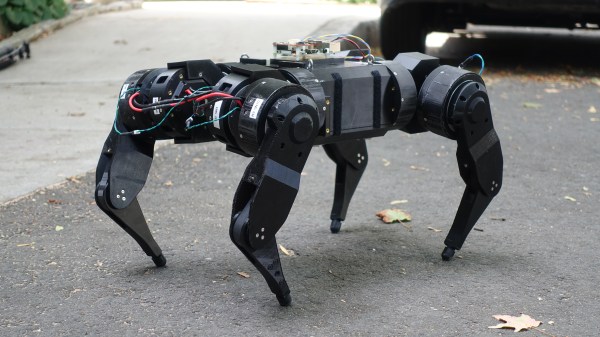
The more we read about [Josh Pieper]’s quadruped, the mjbots quad A0, the more blown away we are by his year of progress on the design. Each part of the robot deserves its own article: from the heavily modified brushless motors (with custom planetary gears) to the custom motor driver designed just for this project.

[Josh], realized early on that the off-the-shelf components like an ODrive just weren’t going to cut it for his application. So he designed his own board, took it through four revisions, and even did thermal and cycle testing on it. He ended up with the compact moteus board. It can pump out 400 Watts of peak power while its 3Mbit control protocol leaves plenty of bandwidth for real time dynamic control.

The motors and gearboxes are also impressive. It took thorough experimenting and taking inspiration from other projects  before he arrived at a 8108 quad copter motor modified and upgraded so heavily its own mother wouldn’t recognize it. This is all packed into a leg unit with three degrees of freedom that puts even the fanciest servo based quadruped to shame.

Finally it’s all packed into a neat four-legged robot frame with batteries and a Pi. You can get a video summary of the robot here or after the break, and we recommend reading his blog for some more images and details.

Continue reading “Amazing Open Source Quadruped Capable Of Dynamic Motion”

Jigsaw Motor Uses PCB Coils For Radial Flux

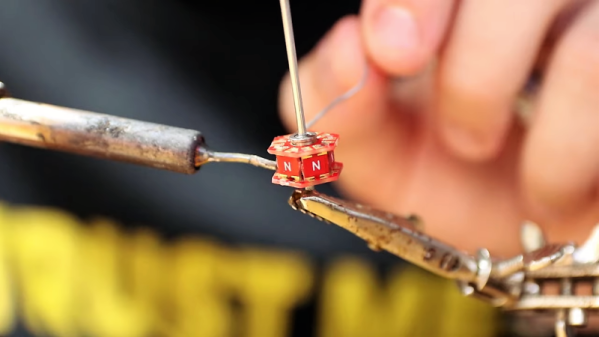
Electric motors are easy to make; remember those experiments with wire-wrapped nails? But what’s easy to make is often hard to engineer, and making a motor that’s small, light, and powerful can be difficult. [Carl Bugeja] however is not one to back down from a challenge, and his tiny “jigsaw” PCB motor is the latest result of his motor-building experiments.

We’re used to seeing brushless PCB motors from [Carl], but mainly of the axial-flux variety, wherein the stator coils are arranged so their magnetic lines of force are parallel to the motor’s shaft – his tiny PCB motors are a great example of this geometry. While those can be completely printed, they’re far from optimal. So, [Carl] started looking at ways to make a radial-flux PCB motor. His design has six six-layer PCB coils soldered perpendicular to a hexagonal end plate. The end plate has traces to connect the coils in a star configuration, and together with a matching top plate, they provide support for tiny bearings. The rotor meanwhile is a 3D-printed cube with press-fit neodymium magnets. Check out the build in the video below.

Connected to an ESC, the motor works decently, but not spectacularly. [Carl] admits that more tweaking is in order, and we have little doubt he’ll keep optimizing the design. We like the look of this, and we’re keen to see it improved.

Continue reading “Jigsaw Motor Uses PCB Coils For Radial Flux”

Robotic Cheetah Teaches A Motors Class

It seems like modern roboticists have decided to have a competition to see which group can develop the most terrifying robot ever invented. As of this writing the leading candidate seems to be the robot that can fuel itself by “eating” organic matter. We can only hope that the engineers involved will decide not to flesh that one out completely. Anyway, if we can get past the horrifying and/or uncanny valley-type situations we find ourselves in when looking at these robots, it turns out they have a lot to teach us about the theories behind a lot of complicated electric motors.

This research paper (gigantic PDF warning) focuses on the construction methods behind MIT’s cheetah robot. It has twelve degrees of freedom and uses a number of exceptionally low-cost modular actuators as motors to control its four legs. Compared to other robots of this type, this helps them jump a major hurdle of cost while still retaining an impressive amount of mobility and control. They were able to integrate a brushless motor, a smart ESC system with feedback, and a planetary gearbox all into the motor itself. That alone is worth the price of admission!

The details on how they did it are well-documented in the 102-page academic document and the source code is available on GitHub if you need a motor like this for any other sort of project, but if you’re here just for the cheetah doing backflips you can also keep up with the build progress at the project’s blog page. We also featured this build earlier in its history as well.

3D Printing A Water Jet Drive

[Ivan Miranda] is always experimenting with 3D printing, and recently has been taking his work on the water. His latest creation is a racing paddle boat, but its performance left [Ivan] with a need for speed. Cue the development of the 3D printed water jet engine (YouTube link, embedded below).

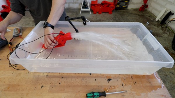
The basic principle of operation is simple. Water is sucked through an inlet, where it is accelerated by a turbine driven by a brushless motor. This turbine, in combination with stator fins, forces the water through the outlet, propelling the boat forwards in the process.

The first prototype is printed in PLA. Tolerances are good, thanks largely to [Ivan]’s experience and well-calibrated printers. After assembly, the engine is fired up, to great results. After sourcing a series of larger tubs in which to test the device, the engine is finally run up to full throttle and appears more than capable of shifting a serious amount of water.

We’d love to see a proper instrumented thrust test, particularly one that compares the device to other water jet drives on the market. Brushless motors make a great drive solution for RC boats, so we’re sure [Ivan] will be tearing up the lake real soon. Video after the break.

Continue reading “3D Printing A Water Jet Drive”

Retired Rideshare Scooter Skips The Reverse Engineering To Ride Again

[Adam Zeloof] (legally) obtained a retired electric scooter and documented how it worked and how he got it working again. The scooter had a past life as a pay-to-ride electric vehicle and “$1 TO START” is still visible on the grip tape. It could be paid for and unlocked with a smartphone app, but [Adam] wasn’t interested in doing that just to ride his new scooter.

His report includes lots of teardown photos, as well as a rundown of how the whole thing works. Most of the important parts are in the steering column and handlebars. These house the battery, electronic speed controller (ESC), and charging circuitry. The green box attached to the front houses a board that [Adam] determined runs Android and is responsible for network connectivity over the cellular network.

To get the scooter running again, [Adam] and his brother [Sam] considered reverse-engineering the communications between the network box and the scooter’s controller, but in the end opted to simply replace the necessary parts with ones under their direct control. One ESC, charger, and cheap battery monitor later the scooter had all it needed to ride again. With parts for a wide variety of electric scooters readily available online, there was really no need to reverse-engineer anything.

Ridesharing scooter startups are busy working out engineering and security questions like how best to turn electric scooters into a) IoT-connected devices, and b) a viable business plan. Hardware gets revised, and as [Adam] shows, retired units can be pressed into private service with just a little work.

The motors in these things are housed within the wheels, and have frankly outstanding price-to-torque ratios. We’ve seen them mated to open-source controllers and explored for use in robotics.

Teardown Shows Why Innovative Designs Sometimes Fail

Some ideas are real head-scratchers from a design standpoint: Why in the world would you do it that way? For many of us, answering that question often requires a teardown, which is what [Ben Katz] did when this PCB motor-powered weed whacker came across his bench. The results are instructive on what it takes to succeed in the marketplace, or in this case, how to fail.

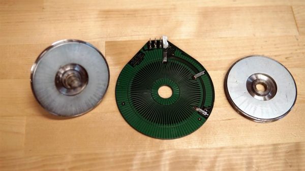
The unit in question comes from an outfit called CORE Outdoor Power. The line trimmer was powered by a big lithium-ion battery pack, but [Ben] concentrated on the unique motor for his teardown. After a problematic entry into the very sturdy case at the far end of the trimmer’s shaft, he found what looks like a souped-up version of [Carl Bugeja]’s PCB brushless motors. The rotors, each with eight large magnets embedded, are sandwiched on either side of a very thick four-layer PCB with intricately etched heavy copper traces. The PCB forms the stator, with four flat coils. The designer pulled a neat trick with the Hall-effect sensors needed for feedback; rather than go with surface-mount sensors, which would add to the thickness of the board, they used through-hole packages soldered to surface pads, with the body of the sensor nestled in a hole in the board. The whole design is very innovative, but sadly, [Ben]’s analysis shows that it has poor performance for its size and weight.

Google around a bit and you’ll see that CORE was purchased some years back by MTD, a big player in the internal combustion engine outdoor power market. They don’t appear to be a going concern anymore, and it looks as though [Ben] has discovered why.

[Jozef] tipped us off to this one. Thanks!

Can You 3D-Print A Stator For A Brushless DC Motor?

Betteridge’s Law holds that any headline that ends in a question mark can be answered with a “No.” We’re not sure that [Mr. Betteridge] was exactly correct, though, since 3D-printed stators can work successfully for BLDC motors, for certain values of success.

It’s not that [GreatScott!] isn’t aware that 3D-printed motors are a thing; after all, the video below mentions the giant Halbach array motor we featured some time ago. But part of advancing the state of the art is to replicate someone else’s results, so that’s essentially what [Scott!] attempted to do here. It also builds on his recent experiments with rewinding commercial BLDCs to turn them into generators. His first step is to recreate the stator of his motor as a printable part. It’s easy enough to recreate the stator’s shape, and even to print it using Proto-pasta iron-infused PLA filament. But that doesn’t come close to replicating the magnetic properties of a proper stator laminated from stamped iron pieces. Motors using the printed stators worked, but they were very low torque, refusing to turn with even minimal loading. There were thermal issues, too, which might have been mitigated by a fan.

So not a stunning success, but still an interesting experiment. And seeing the layers in the printed stators gives us an idea: perhaps a dual-extruder printer could alternate between plain PLA and the magnetic stuff, in an attempt to replicate the laminations of a standard stator. This might help limit eddy currents and manage heating a bit better. Continue reading “Can You 3D-Print A Stator For A Brushless DC Motor?”