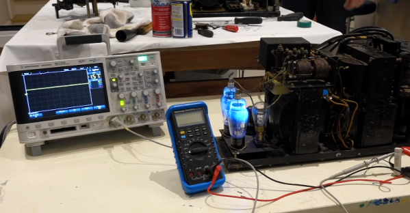
The inside of classic radios holds wonders that the sterile chips and SMD components of today’s circuits can’t hold a candle to. Chunky resistors and capacitors, vacuum tubes with cathodes aglow, and seemingly free-form loops of wire forming inductors will all likely make an appearance. But the most fascinating bit of any old radio was connected to the tuning knob: the big variable capacitor with its interdigitating metal plates. Watching one at work, with its plates evenly and finely spaced, is still a joy to behold.
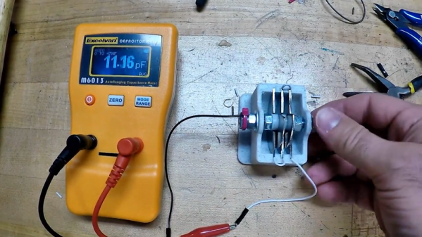
In an attempt to recapture a little of that magic, [Jeremy S. Cook] came up with this home-brew variable tuning capacitor. The frame is built mainly from 3D-printed parts, which supports a shaft made from a common bolt. Plates are fashioned from stainless steel fender washers cut in half; the fixed plates are press-fit into the frame while the rotary plates ride on the shaft. The spacing between the rotary plates is maintained by printed spacers, which also serve to lock the rotor into one solid unit. [Jeremy]’s prototype, for which he provides STL files, can be tuned between about 7 and 15 pF. Check out the build in the video below.
We love the look of this, and we can imagine custom tuning caps would come in handy for certain retro radio builds. The tuning range is a little narrow, but that could be fixed with more plates or closer spacing. That might be a tall order with thick steel washers, but we’ve seen really thin aluminum machined and closely spaced before, so this might be one approach to higher capacitance. Continue reading “DIY Tuning Capacitors From Washers And 3D-Printed Parts”