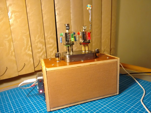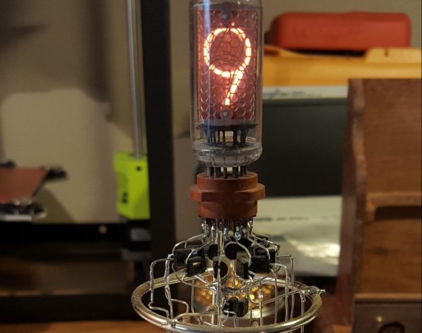
Single tube Nixie clocks? Been there, seen that. A single tube Nixie clock with sculptural wiring that exposes dangerous voltages? Now that’s something you don’t see every day.
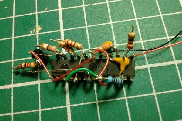
[Andrew Moser]’s clock is clearly a case of aesthetic by anesthetic — he built it after surgery while under the influence of painkillers. That may explain the questionable judgment, but we won’t argue with the look. The boost converter for the Nixie lives near the base of the bent wire frame, with the ATmega 328 and DS1307 RTC supported in the midsection by the leads of attached passive components and jumper wires. A ring at the top of the frame supports the octal socket for the Nixie and a crown of driver transistors for each element.
In the video after the break, [Andrew] speaks of rebuilding this on a PCB. While we’ve seen single tube Nixie PCB clocks before, and we agree that the design needs to be safer, we wouldn’t ditch the dead bug style at all. Maybe just throw the whole thing in a glass bell jar or acrylic tube.
Continue reading “Sculptural Nixie Clock Has Shockingly Exposed Design”