Splitting 3D Prints Into Parts Can Add Strength

One of the great things about 3D printers is their ability to make a single part all at once. Separating a part into multiple pieces is usually done to split up objects that are too big to fit on the 3D printer’s print bed. But [Peter] at Markforged (manufacturers of high-end 3D printers) has a video explaining another reason: multi-part prints can benefit from improved strength.

This part can be easily printed as a single piece, but it can be made nearly twice as strong when printed as two, and combined.

The idea is this: filament-based 3D printers generally create parts that are strongest along their X-Y axis (relative to their manufacture) and weakest in the Z direction. [Peter] proposes splitting a part into pieces with this in mind. Not because the part is inconveniently large or has tricky geometry, but so the individual pieces can be printed in orientations that provide the best mechanical strength.

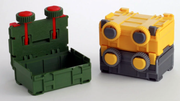
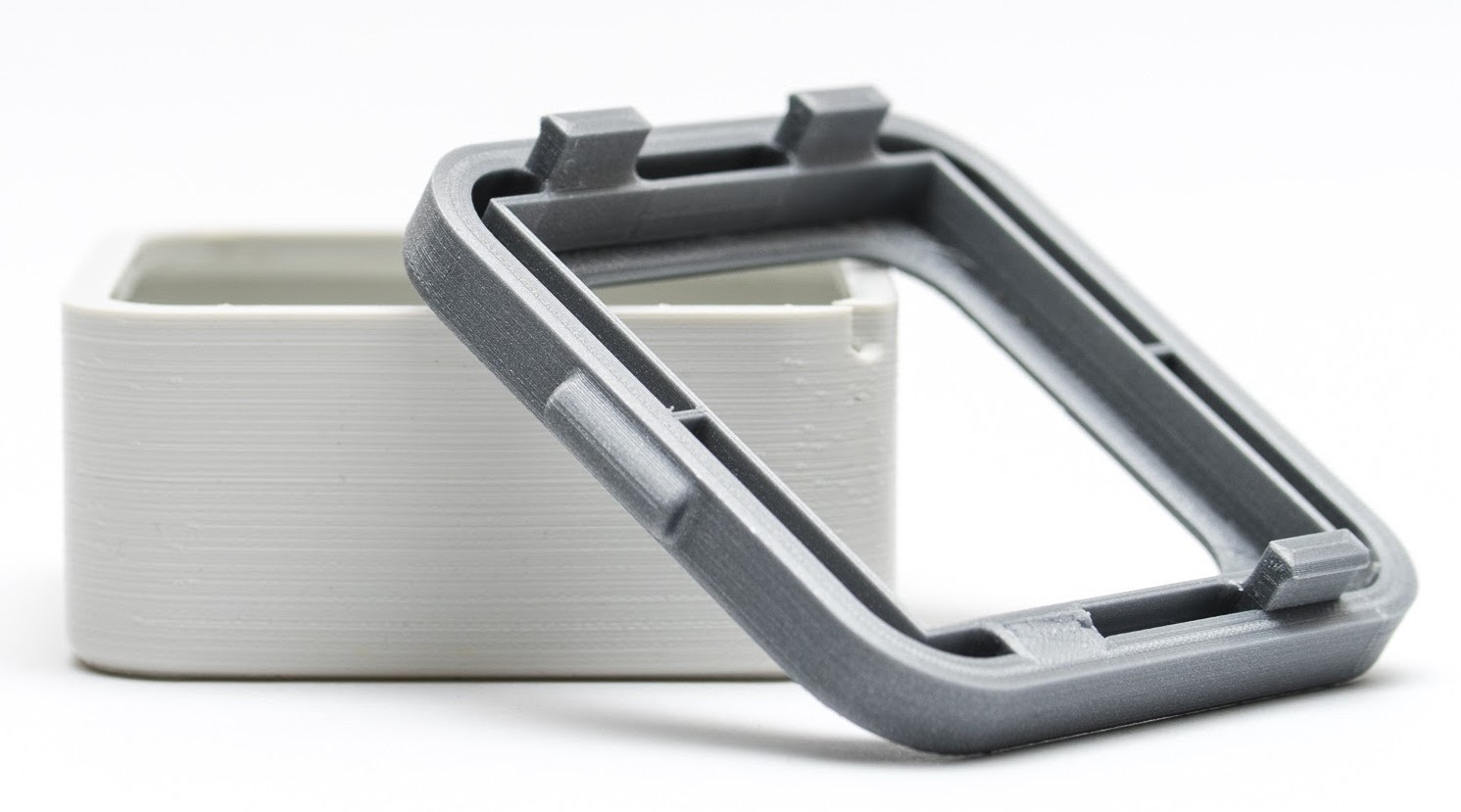
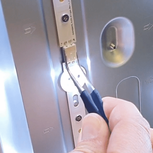
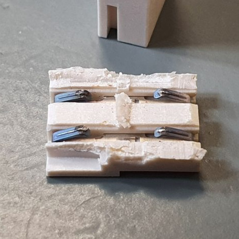
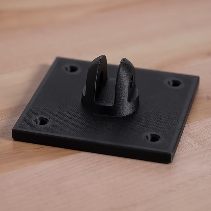
This is demonstrated with the simple part shown here. The usual way to print this part would be flat on a print bed, but by splitting the parts into two and printing each in their optimal orientation, the combined part withstands nearly twice as much force before failing.

[Peter]’s examples use Markforged’s own filaments, but gives advice on more common polymers as well and the same principles apply. This idea is one worth keeping in mind the next time one is seeking to optimize strength. because of how simple it is.

We’ve seen a variety of methods to toughen up or ruggedize prints in the past, but they’re usually more complex (or at least messier.) Examples include embedding braided steel cable, embedding fiberglass mesh, applying electroplating to a printed structure, and plain old embedding some bolts and washers to buffer load-bearing areas.

Continue reading “Splitting 3D Prints Into Parts Can Add Strength”

Small synth held in two hands

3D Printed Synth Kit Shares Product Design Insights

We’ve always been delighted with the thoughtful and detailed write-ups that accompany each of [Tommy]’s synth products, and the background of his newest instrument, the Scout, is no exception. The Scout is specifically designed to be beginner-friendly, hackable, and uses 3D printed parts and components as much as possible. But there is much more to effectively using 3D printing as a production method than simply churning out parts. Everything needed to be carefully designed and tested, including the 3D printed battery holder, which we happen to think is a great idea.

3d printed battery holder, showing inserted spring contacts
3D printed battery holder, with spring contacts inserted by hand.

[Tommy] also spends some time explaining how he decided which features and design elements to include and which to leave out, contrasting the Scout with his POLY555 synth. Since the Scout is designed to be affordable and beginner-friendly, too many features can in fact be a drawback. Component costs go up, assembly becomes less straightforward, and more complex parts means additional failure points when 3D printing.

[Tommy] opted to keep the Scout tightly focused, but since it’s entirely open-sourced with a hackable design, adding features is made as easy as can be. [Tommy] designed the PCB in KiCad and used OpenSCAD for everything else. The Scout uses the ATmega328, and can be easily modified using the Arduino IDE.

STL files can be downloaded here and all source files are on the project’s GitHub repository, which also contains detailed assembly and modification guides. Watch it in action in the video, embedded below.

Continue reading “3D Printed Synth Kit Shares Product Design Insights”

To Lovers Of Small Boxes: A 3D Printable Design Just For You

Print them at 50% scale for a far cuter (and much less useful) result.

[Jacob Stanton]’s design for 3D-printable, stacking and locking boxes is a great example of design for manufacturability (DFM). MicroStacks show how part of good DFM is taking the manufacturing method’s strengths and weaknesses into account. [Jacob]’s boxes are created specifically with 3D printing in mind, which is great design whether somebody is making one, or dozens.

The boxes have sturdy parts that all print without any need for supports, fasteners, or post-processing. In addition, since no two 3D printers are quite alike and some print better than others, the parts are also designed to be quite forgiving of loose tolerances. Even on a printer that is less well-tuned than it could be, the design should still work. The boxes also have a nice stacking feature: a sturdy dovetail combined with a sliding tab means that once boxes are stacked, they’re not coming apart by accident unless something breaks in the process.

The boxes as designed are about big enough to store AA cells. Not the right size for you? One nice thing about a 3D-printable design that doesn’t need supports is that it’s trivial to uniformly scale the size of the models up or down to match one’s needs without introducing any print complications in the process. You can watch [Jacob] assemble and demonstrate his design in the video, embedded below.

Continue reading “To Lovers Of Small Boxes: A 3D Printable Design Just For You”

Peek Into This Synth’s Great Design (And Abandoned Features)

[Tommy]’s POLY555 is an analog, 20-note polyphonic synthesizer that makes heavy use of 3D printing and shows off some clever design. The POLY555, as well as [Tommy]’s earlier synth designs, are based around the 555 timer. But one 555 is one oscillator, which means only one note can be played at a time. To make the POLY555 polyphonic, [Tommy] took things to their logical extreme and simply added multiple 555s, expanding the capabilities while keeping the classic 555 synth heritage.

The real gem here is [Tommy]’s writeup. In it, he explains the various design choices and improvements that went into the POLY555, not just as an instrument, but as a kit intended to be produced and easy to assemble. Good DFM (Design For Manufacturability) takes time and effort, but pays off big time even for things made in relatively small quantities. Anything that reduces complexity, eliminates steps, or improves reliability is a change worth investigating.

For example, the volume wheel is not a thumbwheel pot. It is actually a 3D-printed piece attached to the same potentiometer that the 555s use for tuning; meaning one less part to keep track of in the bill of materials. It’s all a gold mine of tips for anyone looking at making more than just a handful of something, and a peek into the hard work that goes into designing something to be produced. [Tommy] even has a short section dedicated to abandoned or rejected ideas that didn’t make the cut, which is educational in itself. Want more? Good news! This isn’t the first time we’ve been delighted with [Tommy]’s prototyping and design discussions.

POLY555’s design files (OpenSCAD for enclosure and parts, and KiCad for schematic and PCB) as well as assembly guide are all available on GitHub, and STL files can be found on Thingiverse. [Tommy] sells partial and complete kits as well, so there’s something for everyone’s comfort level. Watch the POLY555 in action in the video, embedded below.

Continue reading “Peek Into This Synth’s Great Design (And Abandoned Features)”

Retrotechtacular: Design For Assembly, 1980s-Style

To get its engineers thinking about design for assembly back in the 1980s, Westinghouse made a video about a product optimized for assembly: the IBM Proprinter. The technology may be dated, but the film presents a great look at how companies designed not only for manufacturing, but also for ease of assembly.

It’s not clear whether Westinghouse and IBM collaborated on the project, but given the inside knowledge of the dot-matrix printer’s assembly, it seems like they did. The first few minutes are occupied by an unidentified Westinghouse executive talking about design for assembly in general terms, and how it impacts the bottom line. Skip ahead to 3:41 if talking suits aren’t your thing.

Once the engineer gets going on the printer, though, things get really interesting. The printer’s guts are laid out before him, ready to be assembled. What’s notably absent from the table are tools — the Proprinter was so well designed that the only tool needed is a pair of human hands. And they don’t have to be particularly dexterous hands, either — the design favors motions that are straight down, letting gravity assist the assembly process and preventing assemblers from the need to contort their bodies. Almost everything is held in place by compliant mechanisms built into the plastic parts. There are a few gems in the film, like the plastic lead screw that drives the printhead, obviating the need to string a fussy timing belt, or the unique roller that twists to lock onto a long shaft, rather than having to be pushed to its center.

We found this film which we’ve placed below the break to be very instructive, and the fact that a device as complex as a printer can be assembled in just a few minutes without picking up a single tool is pretty illustrative of the power of designing for assembly. Slick designs that can’t be manufactured at scale are all too common in this age of powerful design tools and desktop manufacturing, so these lessons from the past might be worth relearning.

Continue reading “Retrotechtacular: Design For Assembly, 1980s-Style”

Simple Tips For Better 3D-Printed Enclosures

3D printing can be great for making enclosures, and following some simple guidelines can help the whole process go much smoother. 3D Hubs has an article on designing printed enclosures that has clear steps and tips to get enclosures coming out right the first time. 3D Hubs offers 3D printing and other services, and the article starts with a short roundup of fabrication methods but the rest is a solid set of tips applicable to anyone.

The first recommendation is to model the contents of the enclosure as a way to help ensure everything fits as it should, and try to discover problems as early as possible during the design phase, before anything gets actually printed. We’ve seen how a PCB that doesn’t take the enclosure into account risks needing a redesign, because there are some issues an enclosure just can’t fix.

The rest of their advice boils down to concrete design guidelines about wall thickness (they recommend 2 mm or more), clearances (allow a minimum of 0.5 mm between internal components and enclosure), and how to size holes for fasteners, clips, or ports. These numbers aren’t absolute minimums, but good baseline values to avoid surprises.

One final useful tip is that using a uniform wall thickness throughout the enclosure is general good practice. While this isn’t strictly necessary for successful 3D printing, it will make life easier if the enclosure ever moves to injection molding. Want to know more? Our own Bob Baddeley has an excellent primer on injection molding, and his been-there-done-that perspective is invaluable.

Low-Tech Fix Saves Expensive, High-Tech TV From Junk Pile

Wiggling this connector caused the backlight to turn off and on.

[Tweepy]’s TV stopped working, and the experience is a brief reminder that if a modern appliance fails, it is worth taking a look inside because the failure might be something simple. In this case, the dead TV was actually a dead LED backlight, and the fix was so embarrassingly simple that [Tweepy] is tempted to chalk it up to negligently poor DFM (design for manufacture) at best, or even some kind of effort at planned obsolescence at worst.

What happened is this: the TV appeared to stop working, but one could still make out screen content while shining a bright light on the screen. Seeing this, [Tweepy] deduced that the backlight had failed, and opened up the device to see if it could be repaired. However, the reason for the backlight failure was a surprise. It was not the power supply, nor even any of the LEDs themselves; the whole backlight wouldn’t turn on because of a cheap little PCB-to-PCB connector, and the two small spring contacts inside that had failed.

The failed connector, once cut open, showed contacts in poor condition (click to enlarge). It was ditched for a soldered connection, and the TV lived again.

From the outside things looked okay, but wiggling the connector made the backlight turn on and off, so the connection was clearly bad. Investigating further, [Tweepy] saw that the contact points of the PCBs and the two little conductors inside the connector showed clear signs of arcing and oxidation, leading to a poor connection that eventually failed, resulting in a useless TV. The fix wasn’t to clean the contacts; the correct fix was to replace the connector with a soldered connection.

Using that cheap little connector doubtlessly saved some assembly time at the factory, but it also led to failure within a fairly short amount of time. Had [Tweepy] not been handy with a screwdriver (or not bothered to investigate) the otherwise working TV would doubtlessly have ended up in a landfill.

It serves as a good reminder to make some time to investigate failures of appliances, even if one’s repair skills are limited, because the problem might be a simple one. Planned obsolescence is a tempting doorstep upon which to dump failures like this, but a good case can be made that planned obsolescence isn’t really a thing, even if manufacturers compromising products in one way or another certainly is.