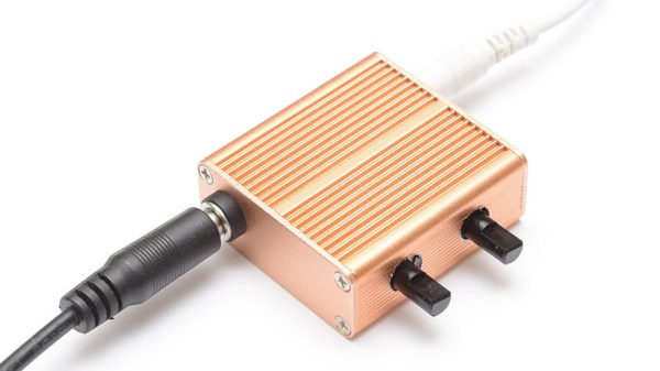
A chaotic drone of meaningless sound to lull the human brain out of its usual drive to latch on to patterns can at times be a welcome thing. A nonsense background din — like an old television tuned to a dead channel — can help drown out distractions and other invading sounds when earplugs aren’t enough. As [mitxela] explains, this can be done with an MP3 file of white noise, and that is a solution that works perfectly well for most practical purposes. However he found himself wanting a more refined hardware noise generator with analog controls to fine tune the output, and so the Rumbler was born.
The Rumbler isn’t just a white noise generator. White noise has a flat spectrum, but the noise from the Rumbler is closer to Red or Brownian Noise. The different colors of noise have specific definitions, but the Rumbler’s output is really just white noise that has been put through some low pass filters to create an output closer to a nice background rumble that sounds pleasant, whereas white noise is more like flat static.
Why bother with doing this? Mainly because building things is fun, but there is also the idea that this is better at blocking out nuisance sounds from neighboring human activities. By the time distant music (or television, or talking, or shouting) has trickled through walls and into one’s eardrums, the higher frequencies have been much more strongly attenuated than the lower frequencies. This is why one can easily hear the bass from a nearby party’s music, but the lyrics don’t survive the trip through walls and windows nearly as well. The noise from the Rumbler is simply a better fit to those more durable lower frequencies.
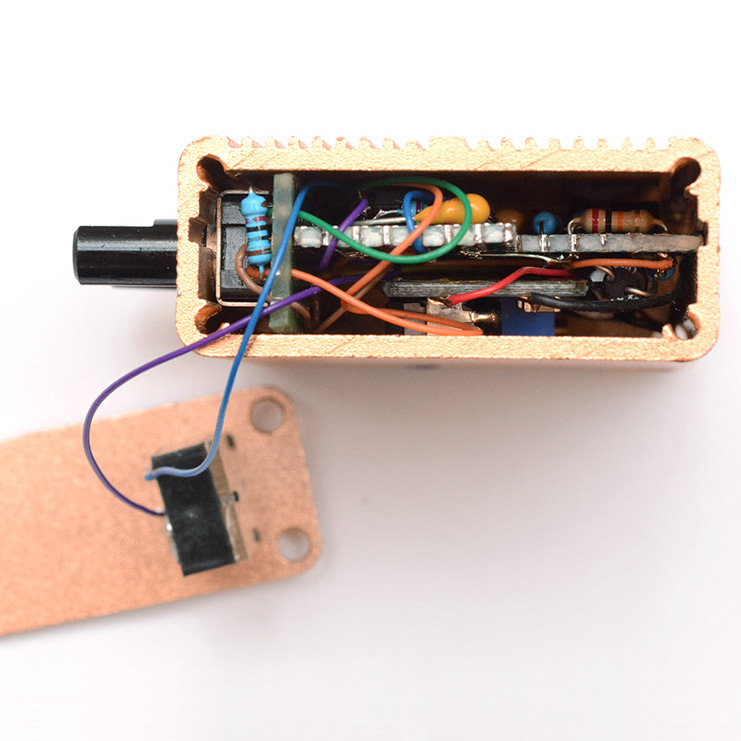
[Mitxela]’s writeup has quite a few useful tips on analog design and prototyping, so give it a read even if you’re not planning to make your own analog noise box. Want to hear the Rumbler for yourself? There’s an embedded audio sample near the bottom of the page, so go check it out.
For a truly modern application of white noise, check out the cone of silence for snooping smart speakers.