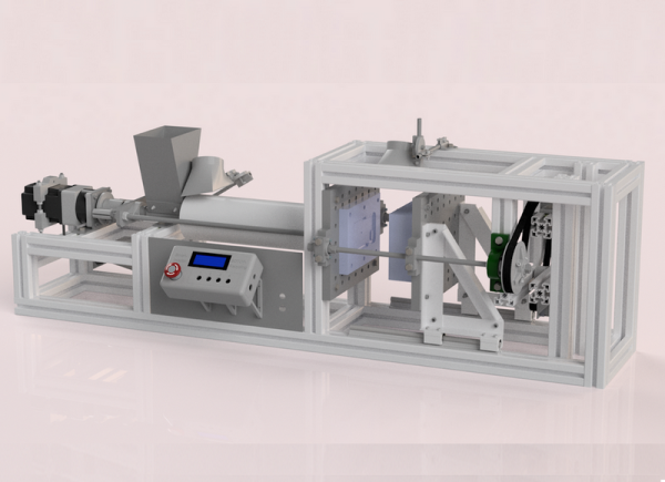
Many people have the means now to create little plastic objects thanks to 3D printing. However, injection molding is far less common. Another uncommon tech is plastic recycling, although we do occasionally see people converting waste plastic into filament. [Manuel] wants to solve both of those problems and created an injection molder specifically for recycling.
The machine — Smart Injector — is automated thanks to an Arduino. It’s pretty complex mechanically, so in addition to CAD models there are several PDF guides and a ton of pictures showing how it all goes together.
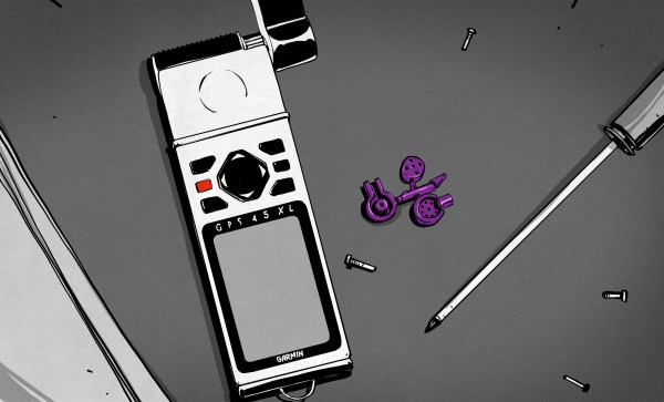
It all started with an 88-ton Arburg RP300 injection molding machine in the basement, and a bit of inattention. Larry Berg wanted a couple custom plastic plugs for his Garmin GPS, so he milled out a mold and ran a few. But he got distracted, and came back an hour later to find that his machine had made 400. Instead of throwing them away, he mailed them away for free, but then he found that people started throwing money at him to make more. People all over the world.
This is how the Purple Open Project turned into an global network of GPS geeks, selling molded alternatives to the oddball Garmin plugs for pledges to pay an unspecified amount, and ended up producing over 350,000 plugs over 16 years before he passed away in 2012. This is the story of a hacker’s hacker, who wanted to be able to connect his GPS to his computer and use it the way he wanted, and accidentally created an international business.
When we think injection molding, the first thing that comes to mind is highly automated production lines pumping out thousands of parts an hour. However, the very same techniques are able to be scaled down to a level accessible by the DIYer, as [The CrafsMan] demonstrates.
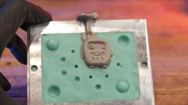
Using a compact, hand-actuated injection moulder, [The Crafsman] demonstrates the basic techniques behind small-scale injection molding. The PIM-Shooter Model 150A in question is designed to work with low melting point plastics like polypropylene and low density polyethylene, and can use aluminium molds which are much cheaper to make than the typical steel molds used in industry.
However, the real game changer is when [The Crafsman] busts out his silicone mold making techniques, and applies them to injection molding. By making molds out of silicone, they can be created far more cheaply and easily without the requirement of heavy CNC machinery to produce the required geometry. With the right attention to detail, it’s possible to get good results without having to invest in a custom aluminium mold at all.
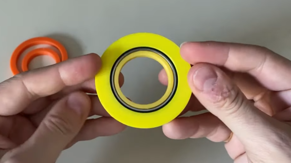
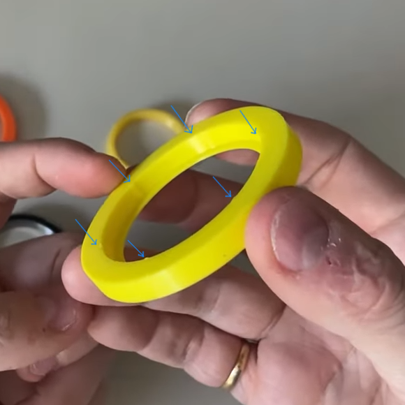
[Dan Royer] shared a tip about how to get a reliably tight fit between 3D printed parts and other hardware (like bearings, for example.) He suggests using crush ribs, a tried-and-true solution borrowed from the world of injection molding and repurposed with 3D printing in mind. Before we explain the solution, let’s first look at the problem a little more closely.
Imagine one wishes to press-fit a bearing into a hole. If that hole isn’t just the right size, the bearing won’t be held snugly. If the hole is a little too big, the bearing is loose. Too small, and the bearing won’t fit at all. Since a 0.1 mm difference can have a noticeable effect on how loose or snug a fit is, it’s important to get it right.
Crush rib locations highlighted with blue arrows.
For a 3D printed object, a hole designed with a diameter of 20 mm (for example) will come out slightly different when printed. The usual way around this is to adjust printer settings or modify the object until the magic combination that yields exactly the right outcome is found, also known as the Goldilocks approach. However, this means the 3D model only comes out right on a specific printer, which is a problem for a design that is meant to be shared. Since [Dan] works on robots with 3D printed elements, finding a solution to this problem was particularly important.
The solution he borrowed from the world of injection molding is to use crush ribs, which can be thought of as a set of very small standoffs that deform as a part is press-fit into them. Instead of a piece of hardware making contact with the entire inside surface of a hole, it makes contact only with the crush ribs. Press fitting a part into crush ribs is far easier (and more forgiving) than trying to get the entire mating surface exactly right.
Using crush ribs in this way is a bit of a hack since their original purpose in injection molding is somewhat different. Walls in injection-molded parts are rarely truly flat, because that makes them harder to eject from a mold. Surfaces therefore have a slight cant to them, which is called a draft. This slight angle means that press fitting parts becomes a problem, because any injection-molded hole will have slanted sides. The solution is crush ribs, which — unlike the walls — are modeled straight. The ribs are small enough that they don’t have an issue with sticking in the mold, and provide the mating surface that a press-fit piece of hardware requires. [Dan] has a short video about applying this technique to 3D printed objects, embedded below.
Hackaday editors Elliot Williams and Mike Szczys are enamored by this week’s fabrication hacks. There’s a PCB mill that isolates traces by scratching rather than cutting. You won’t believe how awesome this angle-cutter jig is at creating tapered augers for injection molding/extruding plastic. And you may not need an interactive way to cut foam, but the art from the cut pieces is more than a mere shadow of excellence. Plus we gab about a clever rotary encoder circuit, which IDE is the least frustrating, and the go-to tools for hard drive recovery.
Take a look at the links below if you want to follow along, and as always, tell us what you think about this episode in the comments!
Take a look at the links below if you want to follow along, and as always, tell us what you think about this episode in the comments!
[Zach] over at his channel Breaking Taps has put up an extraordinary account on manufacturing some homemade acrylic lenses. In the end, not only does he produce some beautiful concave lenses, he also covers the complete manufacturing process, from milling the aluminium die used for injection moulding to tweaking the parameters associated with injecting the actual acrylic, he even goes over the limitations of optics produced in this fashion.
What caught our eye in particular, was how [Zach] used the finished product to practically demonstrate photoelasticity originating from the stress induced by the moulding process. You might be familiar with describing the optical properties of a material by a single number, i.e its permittivity. But what happens if in addition to altering speed, the material also alters the polarisation and direction of light depending on the stress distribution within the material? Whilst a quantitative answer gets a bit complicated you can check out [Zach’s] additional videos to visualise the answer in a pretty and colourful way, without resorting to fancy computer simulations! If however, you really want to persist with the simulation route, check out our article on stress analysis in a totally different setting using Finite Element Analysis.
When it comes to manufacturing, sheet metal and injection molding make the world go ’round. As a manufacturing method, injection molding has its own range of unique design issues and gotchas that are better to be aware of than not. To help with this awareness, [studiored] has a series of blog posts describing injection molding design issues, presented from the perspective of how to avoid and address them.
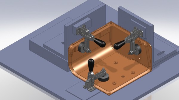
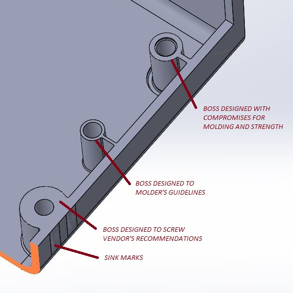
Design of screw bosses demonstrating conflict between molder’s guidelines and vendor’s recommendations. Compromising between both is a science and an art.
Because injection molding involves heat, warp is one issue to be aware of and its principles will probably be familiar to anyone with nitty-gritty experience in 3D printing. Sink marks are also an issue that comes down to differential cooling causing problems, and can ruin a smooth and glossy finish. Both of these play a role in how best to design bosses.
Minimizing and simplifying undercuts (similar to overhangs in 3D printer parlance) is a bit more in-depth, because even a single undercut means much more complex tooling for the mold. Finally, because injection molding depends on reliably molding, cooling, and ejecting parts, designing parts with draft (a slight angle to aid part removal) can be a fact of life.
[studiored] seems to have been working overtime on sharing tips for product design and manufacture on their blog, so it’s worth keeping an eye on it for more additions. We mentioned earlier that much of the manufacturing world revolves around injection molding and sheet metal, so to round out your knowledge we published a primer on everything you need to know about the art and science of bending sheet metal. With a working knowledge of the kinds of design issues that affect these two common manufacturing methods, you’ll have a solid foundation for any forays into either world.