3D Printed Printing Plates Made Using Modern Tools

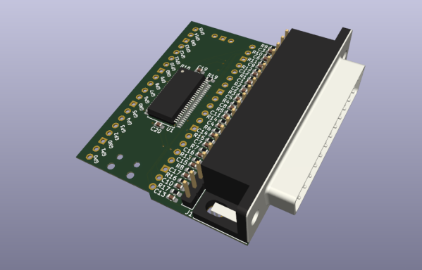
It’s widely accepted that the invention of the printing press by Gutenberg in the 15th Century was the event that essentially enabled the development of the modern world, allowing access to knowledge beyond anything that came before, even if the Chinese got in on the bookmaking act some 500 years previously. Fast-forward a few centuries more and we’ve got the ability to design electronics from our arm chairs, we can print 3D objects from a machine on the coffee table, and 3D modeling can be done by your kids on a tablet computer. What a time to be alive! So we think it’s perfectly fine that [Kris Slyka] has gone full circle and used all these tools to make printing plates for a small press, in order to produce cards for her Etsy business.

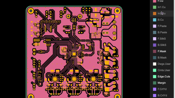
Now before you scoff, yes she admits quite quickly that KiCAD wasn’t the best choice for designing the images to print, since she needed to do a lot of post-processing in Inkscape, she could have just dropped the first step and started in Inkscape anyway. You live and learn. Once the desired image was fully vectorised, it was popped into OpenSCAD in order to extrude it into 3D, thickening the contact to the base to improve the strength a little.

[Kris] demonstrates using the registration marks to align the front and rear side plates, and even (mostly) manages adding a second colour infill for a bit more pizzazz. The results look a little bit wonky and imperfect, exactly what you want for something supposed to be handmade. We think it’s a nice result, even if designing it in KiCAD was a bit bonkers.

For those interested in the OpenSCAD code, have a butchers at this gist. This project is not the first 3D-printed printing press we’ve covered, checkout the Hi-Bred for an example, and here’s the Open Press Project if you’re still interested.

Continue reading “3D Printed Printing Plates Made Using Modern Tools”

an image of kicad's homepage

KiCad Team Releases Warning Regarding Domain Name

On October 19th, [Seth_h] from the KiCad Project posted on the KiCad forums that the project’s original domain name kicad-pcb.org has been unexpectedly sold to a third party, and urged members of the community to avoid any links to this old website.

KiCad has used the domain kicad-pcb.org since 2012 as the official source for information on and downloads of their popular open-source electronics design software. Unfortunately, the original domain name was purchased before KiCad was formalized as an organization, so it was not directly under their control. This all came to head when the old domain name was unexpectedly sold to an unnamed third party that was not affiliated with the project. Currently, the old domain is just a website covered in ads, but the KiCad team fears that it may be used maliciously in the future.

With KiCad’s popularity, thousands of tutorials, articles, and project guides over the years have included links to the old KiCad domain. A Google search in October 2021 found more than 19,000 instances of the old domain spread across the internet. [Seth_h] has called upon the community to make every effort possible to update old links, reducing the chance that people stumble across the wrong website.

[Editor’s Note: We think we got ’em all, let us know if we missed any.]

Luckily, Digikey has swooped in to help save the day. They purchased a new domain, kicad.org, from squatters and donated it to the KiCad Project. (Update: Digi-key donated the KiCad.org domain back in October of 2020 after noticing fishy squatters going back to at least 2016) [Seth_h] explains in his post that a number of safeguards have been put in place to prevent this from happening in the future, including not having the domain name owned by a single person, and having all KiCad trademarks registered to the Linux Foundation.

There’s a good reason why KiCad has gotten so popular, it is packed full of great features for PCB design. Check out our coverage of some of the new features we are most excited for in KiCad 6.0 here.

Highly Configurable Open Source Microscope Cooked Up In FreeCAD

What do you get when you cross a day job as a Medical Histopathologist with an interest in 3D printing and programming? You get a fully-baked Open Source microscope, specifically the Portable Upgradeable Modular Affordable (or PUMA), that’s what. And this is no toy microscope. By combining a sprinkle of off-the-shelf electronics available from pretty much anywhere, a pound or two of filament, and a dash of high quality optical parts, PUMA cooks up quite possibly one of the best open source microscopy experiences we’ve ever tasted.

GitHub user [TadPath] works as a medical pathologist and clearly knows a thing or two about what makes a great instrument, so it is a genuine joy for us to see this tasty project laid out in such a complete fashion. Many a time we’ve looked into an high-profile project, only to find a pile of STL files and some hard to source special parts. But not here. This is deliberately designed to be buildable by practically anyone with access to a 3D printer and an eBay account.

The project is not currently certified for medical diagnostics use, but that is likely only a matter of money and time. The value for education and research (especially in developing nations) cannot really be overstated.

A small selection of the fixed and active aperture choices

The modularity allows a wide range of configurations from simple ambient light illumination, with a single objective, great for using out in the field without electricity, right up to a trinocular setup with TFT-based spatial light modulator enabling advanced methods such as Schlieren phase contrast (which allows visualisation of fluid flow inside a live cell, for example) and a heads-up display for making measurements from the sample. Add into the mix that PUMA is specifically designed to be quickly and easily broken down in the field, that helps busy researchers on the go, out in the sticks.

The GitHub repo has all the details you could need to build your own configuration and appropriate add-ons, everything from CAD files (FreeCAD source, so you can remix it to your heart’s content) and a detailed Bill-of-Materials for sourcing parts.

We covered fluorescence microscopy before, as well as many many other microscope related stories over the years, because quite simply, microscopes are a very important topic. Heck, this humble scribe has a binocular and a trinocular microscope on the bench next to him, and doesn’t even consider that unusual. If you’re hungry for an easily hackable, extendable and cost-effective scope, then this may be just the dish you were looking for.

Continue reading “Highly Configurable Open Source Microscope Cooked Up In FreeCAD”

Tool Generates Interactive PCB Diagrams From KiCAD

Nearly everyone likes nice pinout diagrams, but the more pins and functions are involved, the more cluttered and less useful the diagram becomes. To address this, [Jan Mrázek] created Pinion, a tool to help generate interactive diagrams from KiCad design files.

The result is an interactive diagram that can be viewed in any web browser. Hovering over a pin or pad highlights those signals with a callout for the name, and clicking makes it stay highlighted for easier reference. Further information can be as detailed or as brief as needed.

Interestingly, Pinion isn’t a web service that relies on any kind of backend. The diagrams are static HTML and JavaScript only, easily included in web pages or embedded in GitHub documentation.

If you think Pinion looks a bit familiar, you’re probably remembering that we covered [Jan]’s much earlier PcbDraw tool, which turned KiCad board files into SVG renderings but had no ability to add labels or interactivity. Pinion is an evolution of that earlier idea, and its diagrams are able to act as both documentation and interactive reference, with no reliance on any kind of external service.

Interested? Pinion has a full tutorial and demo and a growing library of parts, so check it out.

WiFiWart Linux Pentesting Device Gets First PCBs

When we last checked in on the WiFiWart, an ambitious project to scratch-build a Linux powered penetration testing drop box small enough to be disguised as a standard phone charger, it was still in the early planning phases. In fact, the whole thing was little more than an idea. But we had a hunch that [Walker] was tenacious enough see the project through to reality, and now less than two months later, we’re happy to report that not only have the first prototype PCBs been assembled, but a community of like minded individuals is being built up around this exciting open source project.

Now before you get too excited, we should probably say that the prototypes didn’t actually work. Even worse, the precious Magic Smoke was released from the board’s Allwinner A33 ARM SoC when a pin only rated for 2.75 V was inadvertently fed 3.3 V. The culprit? Somehow [Walker] says he mistakenly ordered a 3.3 V regulator even though he had the appropriate 2.5 V model down in the Bill of Materials. A bummer to be sure, but that’s what prototypes are for.

Even though [Walker] wasn’t able to fire the board up, the fact that they even got produced shows just how much progress has been made in a relatively short amount of time. A lot of thought went into how the 1 GB DDR3 RAM would get connected to the A33, which includes a brief overview of how you do automatic trace length matching in KiCad. He’s also locked in component selections, such as the RTL8188CUS WiFi module, that were still being contemplated as of our last update.

Multiple boards make better use of vertical space.

Towards the end of the post, he even discusses the ultimate layout of the board, as the one he’s currently working on is just a functional prototype and would never actually fit inside of a phone charger. It sounds like the plan is to make use of the vertical real estate within the plastic enclosure of the charger, rather than trying to cram everything into a two dimensional design.

Want to get in on the fun, or just stay updated as [Walker] embarks on this epic journey? Perhaps you’d be interested in joining the recently formed Open Source Security Hardware Discord server he’s spun up. Whether you’ve got input on the design, or just want to hang out and watch the WiFiWart get developed, we’re sure he’d be happy to have you stop by.

The first post about this project got quite a response from Hackaday readers, and for good reason. While many in the hacking and making scene only have a passing interest in the security side of things, we all love our little little Linux boards. Especially ones that are being developed in the open.

Surf’s Up, A Styrofoam Ball Rides The Waves To Create A Volumetric Display

We are big fans of POV displays, particularly ones that move into 3D. To do so, they need to move even faster than their 2D cousins. [danfoisy] built a volumetric display that doesn’t move LEDs or any other digital display through space, or project light onto a moving surface. All that moves here is a bead of styrofoam and does so at up to 1 meter per second. Having low mass certainly helps when trying to hit the brakes, but we’re getting ahead of ourselves.

danfoisy vdatp 3d simulation

[danfoisy] and son built an acoustic levitator kit from [PhysicsGirl] which inspired the youngster’s science fair project on sound. See the video by [PhysicsGirl] for an explanation of levitation in a standing wave. [danfoisy] happened upon a paper in the Journal Nature about a volumetric display that expanded this one-dimensional standing wave into three dimensions. The paper described using a phased array of ultrasonic transducers, each with a 40 kHz waveform.

After reading the paper and determining how to recreate the experiment, [danfoisy] built a 2D simulation and then another in 3D to validate the approach. We are impressed with the level of physics and programming on display, and that the same code carried through to the build.

[danfoisy] didn’t stop with the simulations, designing and building control boards for each 100 x 100 10 x 10 grid of transducers. Each grid is driven by 2 Intel Cyclone FPGAs and all are fed 3D shapes by a Raspberry Pi Zero W. The volume of the display is 100 mm x 100 mm x 145mm and the positioning of the foam ball is accurate down to .01 mm though currently there is considerable distortion in the positioning.

Check out the video after the break to see the process of simulating, designing, and testing the display. There are a number of tips along the way, including how to test for the polarity of the transducers and the use of a Python script to place the grids of transducers and drivers in KiCad.

danfoisy vdatp schematic  danfoisy vdatp board layout

Continue reading “Surf’s Up, A Styrofoam Ball Rides The Waves To Create A Volumetric Display”

chadaustin's sculpt keyboard test pads wired to protonC

Tether Tames Temperamental Typing

[chadaustin] has a favorite keyboard with a great ergonomic shape, key travel distance, and size, but after switching to Windows 10, the wireless connection introduced a terrible delay. Worse yet, the receiver is notoriously susceptible to interference from USB 3.0 hubs. To provide 128-bit AES encryption, the receiver is paired with the keyboard at the factory and cannot be replaced. If you lose that, you gain a highly ergonomic paper-weight. The solution for [chadaustin] was tethering the keyboard and receive several crash-courses in hardware hacking along the way. As evidenced by the responses to this project on ycombinator, many long-time fans of the Microsoft Sculpt Ergonomic Keyboard, introduced in 2013, suffer similar issues.

chadaustin's sculpt keyboard USB board layout
KiCad USB controller board layout

We really appreciate that [chadaustin] took an incremental approach, tackling one problem at a time and getting help from others along the way for first attempts at many complex steps. The proof-of-concept involved hand-soldering each lead from the keyboard matrix’s test pads to a QMK Proton C, which worked but couldn’t fit inside the keyboard’s case. For a more permanent and tidy solution, [chadaustin] tried a ribbon-cable breakout board and other microcontrollers, but none of those were compact enough to fit inside the case either. This required a custom PCB, another first for [chadaustin].

After a one-day intro to KiCad, [chadaustin] dug into the datasheets, completed a schematic for the board, and generously shared the process of choosing components and creating the layout. [chadaustin] ordered a board and found the mounting holes’ placement needed to be shifted.

With the full matrix mapped by [johnmilkspill], flashing QMK onto the AT90USB1286 controller went fairly smoothly. [chadaustin] chose to map both sides of the split spacebar back to the space key but did add a feature by repurposing the battery indicator LED to Caps Lock. And the results?

chadaustin's sculpt keyboard USB controller fit into case
USB controller fits into the plastic case, wires added to ISP for bootloader button

According to testing done with Is It Snappy?, the latency dropped from the wireless 78 ms down to 65 ms over USB. More importantly, this latency is now consistent, unaffected by USB hubs, and there is no receiver to lose. Of course, [chadaustin] has ideas for future improvement, including regaining the multimedia function keys, as these kinds of hacks are never really done; they are just in the current revision. No word on the fate of the detached number pad, but that likely needs its own tether and is a project for another day.

Thanks for the tip [Linus Söderlind]