Op-Amp Challenge: A Logic-Free BCD

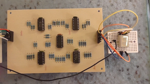
Of digital electronics, a wise man once said that “Every idiot can count to one.” Truer words have rarely been spoken, because at the end of the day, every digital circuit is really just an analog circuit with the interesting bits abstracted away. And to celebrate that way of looking at things, we’re pleased to present this BCD to seven-segment converter that uses no logic chips.

With cheap and easily available chips that perform this exact job, it might seem a little loopy to throw 20 LM324 op-amps at the job. But as [gschmidt958] explains, this is strictly for the challenge, plus it made a nice entry in the recently concluded Op-Amp Challenge contest. His work began in simulation, exploring op-amp versions of the basic logic gates — NAND, AND, OR, and NOT — all of which rely on using the LM324s as comparators. There were real-world curveballs, of course, not least of which was running out of the 10k resistors used for input averaging. Another plot twist was running out of time to order a PCB, which required designing one using MS Paint and etching it at home.

The demo video below shows the circuit at work, taking the BCD output of a 74HC393 counter — clocked by a 555, naturally — and driving a seven-segment LED.  It’s honestly a lot of work for such a simple task, but there’s something satisfying about the whole project. We think [Widlar] would be proud.

Continue reading “Op-Amp Challenge: A Logic-Free BCD”

Hackaday Prize 2023: Building A Relay ALU

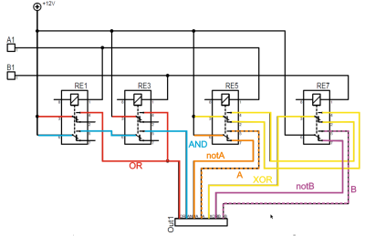
There’s much truth in the advice that, to truly understand something, you need to build it yourself from the ground up. That’s the idea behind [Christian]’s entry for the Re-engineering Education category of the 2023 Hackaday Prize. Built as an educational demonstrator, this is a complete arithmetic-logic unit (ALU) using discrete relays — and not high-density types either — these are the big honking clear-cased kind.

The design is neatly, intentionally, partitioned along functional lines, with four custom PCB designs, each board operating on 4-bits. To handle a byte-length word, boards are simply cascaded, making a total of eight. The register, adder, logic function, and multiplex boards are the heart of the build with an additional two custom boards for visualization (using an Arduino for convenience) and IO forming the interface. After all, a basic CPU is just an ALU and some control around it, the magic is really in the ALU.

The fundamental logical operations operating upon two operands, {A, B} are A, ~A, B, ~B, A or B, A and B, A xor B, can be computed from just four relays per bit. The logic outputs do need to be fed into a 7-to-1 bit selector before being fed to the output register, but that’s the job of a separate board. The adder function is the most basic, simply a pair of half-adders and an OR-gate to handle the chaining of the carry inputs and generate the carry chain output.



3D printed cable runs are a nice touch and make for a slick wiring job to tie it all together.

For a more complete relay-based CPU, you could check out the MERCIA relay computer project, not to mention this wonderfully polished build.


ChatGPT Powers A Different Kind Of Logic Analyzer

If you’re hoping that this AI-powered logic analyzer will help you quickly debug that wonky digital circuit on your bench with the magic of AI, we’re sorry to disappoint you. But if you’re in luck if you’re in the market for something to help you detect logical fallacies someone spouts in conversation. With the magic of AI, of course.

First, a quick review: logic fallacies are errors in reasoning that lead to the wrong conclusions from a set of observations. Enumerating the kinds of fallacies has become a bit of a cottage industry in this age of fake news and misinformation, to the extent that many of the common fallacies have catchy names like “Texas Sharpshooter” or “No True Scotsman”. Each fallacy has its own set of characteristics, and while it can be easy to pick some of them out, analyzing speech and finding them all is a tough job.

Continue reading “ChatGPT Powers A Different Kind Of Logic Analyzer”

Retrotechtacular: Critical Code Reading, 70s Style

Anyone who has ever made a living writing code has probably had some version of the following drilled into their head: “Always write your code so the next person can understand it.” Every single coder has then gone on to do exactly the opposite, using cryptic variables and bizarre structures that nobody else could possibly follow. And every single coder has also forgotten the next part of that saying — “Because the next person could be you” — and gone on to curse out an often anonymous predecessor when equally inscrutable code is thrust upon them to maintain. Cognitive dissonance be damned!

It’s a tale as old as time, or at least as old as programming has existed as a profession. And by 1975, poorly written code was enough of a problem that an outfit called Edutronics put together the animated gem Critical Program Reading: Structuring an Unstructured Program. It’s apparently Part 1 of a larger series on structured programming techniques, and comes to us by way of [Alec Watson], host of Technology Connections on YouTube, by way of his second channel, the delightfully named Technology Connextras.

The film’s three minimally animated characters, each of whom could have been the villain in an episode of Scooby Doo, are tasked by a stern-sounding narrator to analyze a fragment of pseudocode that’s written in a concoction of COBOL, PL/1, and a bunch of other languages. The code is a hot mess, but our heroes muddle through it line by awful line, making it more readable by guessing at more descriptive variable names, adding structured elements, and making logical changes to improve the program’s flow. The example code is highly contrived, to be sure, but the business logic becomes much clearer as our team refactors the code and makes it far more approachable.

For as much as languages have changed since the 1970s, and with all the progress we’ve made in software engineering, the lessons presented in this film are still surprisingly relevant. We loved a lot of the little nuggets dropped along the way, like “Consistency aids understanding,” and “Use symbols in a natural way.” But we will take exception with the statement “Wrong means poor structure” — we’ve written seen plenty of properly structured code that didn’t work worth a damn. We also enjoyed the attempt at socially engineering a less toxic work environment: “Use tact in personal criticisms.” If only they could learn that lesson over at Stack Overflow.

It’s not clear where [Alec] found this 16-mm film — we’d sure like to hear that story — but it’s a beauty and we’re glad he took the time to digitize it. We’re consistently amazed at his ability to make even the most mundane aspects of technology endlessly fascinating, and while this film may be a bit off from his normal fare, it’s still a great find. Continue reading “Retrotechtacular: Critical Code Reading, 70s Style”

Logic Gate Game Is Fun AND Educational

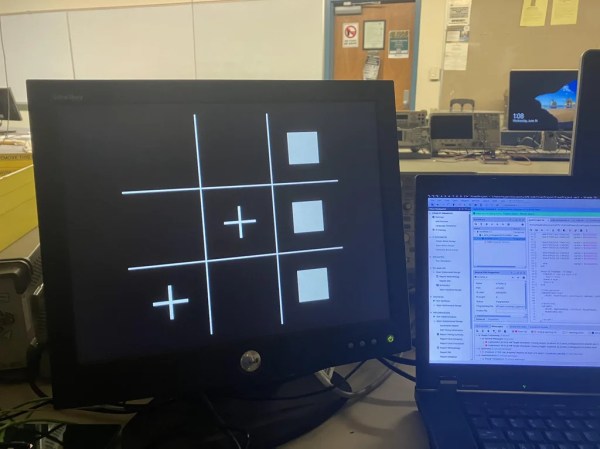
How well do you know your logic gates? For their final submission for STEM Projects class, [BKriet] gamified the situation using a Raspberry Pi Pico, some blinkenlights, and a not-insignificant amount of 3D printing. The result is Name! That! Gate!, a fun and educational toy that [BKriet] ultimately donated back to the class (that’s a hot move in our book).

The objective of this game is to figure out which logic gate is being used to make the output shown on the screen, given A, B, and/or C as inputs. There are ten stages to the game, and each correct stage awards the player 14 points, for a perfect score of 140. Although a random gate is loaded for every stage, code ensures that no gate is ever repeated during a single game.

This project is completely open source, so the gate is wide open. Don’t have a 3D printer? Here’s a big set of PCB logic gates, but really, you can make logic gates out of almost anything.

Should’ve Used A 555 — Or 276 Of Them

When asked to whip up a simple egg timer, most of us could probably come up with a quick design based on the ubiquitous 555 timer. Add a couple of passives around the little eight-pin DIP, put an LED on it to show when time runs out, and maybe even add a pot for variable timing intervals if we’re feeling fancy. Heck, many of us could do it from memory.

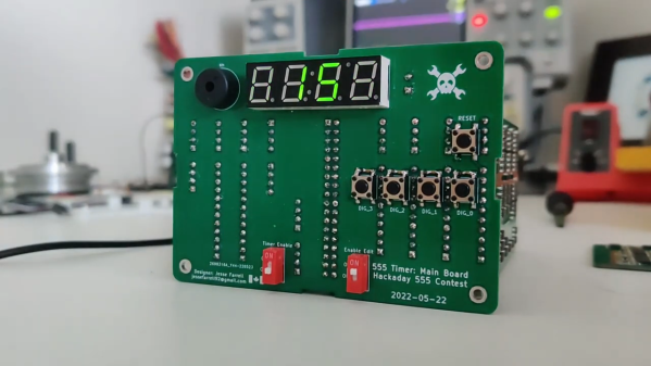
So why exactly did [Jesse Farrell] manage to do essentially the same thing using a whopping 276 555s? Easy — because why not? Originally started as an entry in the latest iteration of our 555 Contest, [Jesse]’s goal was simple — build a functional timer with a digital display using nothing but 555s and the necessary passives. He ended up needing a few transistors and diodes to pull it off, but that’s a minor concession when you consider how many chips he replaced with 555s, including counters, decoders, multiplexers, and display drivers. All these chips were built up from basic logic gates, a latch, and a flip-flop, all made from one or more 555s, or variants like the 556 or 558.

As one can imagine, 276 chips take a lot of real estate, and it took eleven PCBs to complete the timer. A main board acts as the timer’s control panel as well as serving as a motherboard for ten other cards, each devoted to a different block of functions. It’s all neat and tidy, and very well-executed, which is in keeping with the excellent documentation [Jesse] produced. The whole thing is wonderfully, needlessly complex, and we couldn’t be more tickled to feature it.

Continue reading “Should’ve Used A 555 — Or 276 Of Them”

Mysterious Adder From 1960s Bendix G-20

[David Lovett] aka Usagi Electric is taking a dive into yet another old computer design, this one from the early 1960s. He recently obtained eight mystery circuit boards on-loan for the purpose of reverse engineering them. It turns out these came from an old mainframe called the Bendix G-20, a successor to the 1965 G-15 vacuum tube model. The cards are:

  • Full Adder
  • AND Gate
  • OR Gate
  • Emitter Follower
  • Flip Flop
  • Quad Inverting Amplifier
  • DLO Amplifier
  • Gated CPA

Most of these are pretty straightforward to figure out, but he ran into some troubles trying to understand the full adder board. The first issue is there is some uncertainty surrounding the logic level voltages. This system uses negative voltages, with -3.5 V representing a logic 1 … or is it a logic 0? And even taking into account this ambiguity, [David] is having a hard time deciphering how the adder works. It uses a bunch of diodes to implement a logic lookup table of an adder — except he is not able to make it match any known addition scheme. [David] has called out to the community for help on this one, and if you have any ideas how this adder works, visit his wiki linked above for more information and give him shout.

We don’t know how [David] squeezes in the time for these side projects, when he is so busy on the Centurion mini-computer restoration and the monstrous single-bit vacuum tube computer he is building.

Continue reading “Mysterious Adder From 1960s Bendix G-20”