There are lots of laser cutters and other CNC machines available for a decent price online, but the major hurdle to getting these machines running won’t be the price or the parts. It’s usually the controller PC, which might be running Windows XP or NT if you’re lucky, but some of them are still using IBM XT computers from the ’80s. Even if the hardware in these machines is working, it might be impossible to get the software, and even then it will be dated and lacking features of modern computers. Enter the Super Gerbil.
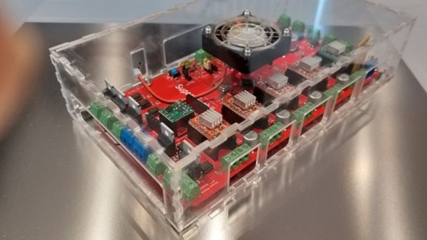
[Paul] was able to find a laser cutter with one of these obsolete controllers, but figured there was a better way to getting it running again. As the name suggests, it uses GRBL, a G-Code parser and CNC controller software package that was originally made to run on an 8-bit AVR microcontroller, but [Paul] designed the Super Gerbil to run on a 32 bit ARM platform. He also added Z-axis control to it, so it now sports more degrees of freedom than the original software.
By way of a proof of concept, once he was finished building the Super Gerbil he ordered a CNC machine from China with an obsolete controller and was able to get it running within a day. As an added bonus, he made everything open so there are no license fees or cloud storage requirements if you want to use his controller. [Paul] also has a Kickstarter page for this project as well. Hopefully controllers haven’t been the only thing stopping you from getting a CNC machine for your lab, though, but if they have you now have a great solution for a 3040 or 3020 CNC machine’s controller, or any other CNC machine you might want to have. Continue reading “Replace Legacy CNC PCs With A Gerbil”