3D Printing Metal In Mid Air

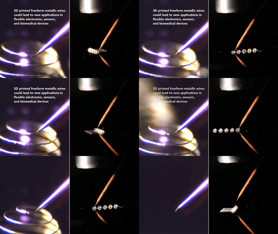
Published only 3 days before our article on how it is high time for direct metal 3D printers, the folks at Harvard have mastered 3D metal printing in midair with no support (as well as time travel apparently). Because it hardens so quickly, support isn’t necessary, and curves, sharp angles, and sophisticated shapes are possible.

The material is silver nanoparticles extruded out of a nozzle, and shortly after leaving it is blasted with a carefully programmed laser that solidifies the material. The trick is that the laser can’t focus on the tip of the nozzle or else heat transfer would solidify the ink inside the nozzle and clog it. In the video you can see the flash from the laser following slightly behind. The extrusion diameter is thinner than a hair, so don’t expect to be building large structures with this yet.

If you want big metal 3D printing, you should probably stick to the welders attached to robotic arms.

Continue reading “3D Printing Metal In Mid Air”

Hexagon Cake Cutting

Cake Knife Tessellates Cake

Rectangles? Squares? Pie slices? Who says dessert has to come in that shape? Why not triangles, circles, or even hexagons? Master of all things woodworking [Matthias Wandel] decided to solve this problem, and delved into a bit of metal working.

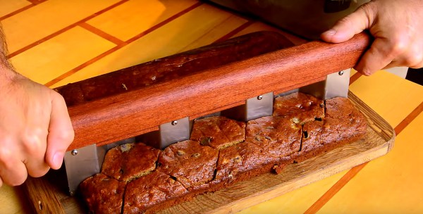
Using a strip of 26 gauge stainless steel, [Matthias] threw together some wood clamps in order to bend the metal into funky looking blade. He then put slits into a nice wooden handle and assembled the whole thing with a very slight positive curve, allowing you to roll the knife as you cut your confectionery.

As you can see in the following video, it works pretty well — and always, it’s a pleasure to see this man work.

Continue reading “Cake Knife Tessellates Cake”

From Scrap To Sword: Casting Pewter

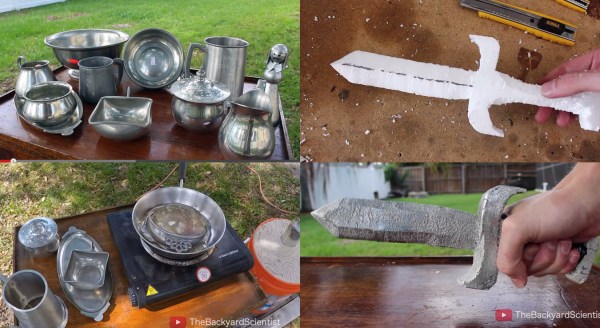
[TheBackyardScientist] has been living up to his name, this time by casting a pewter sword in his yard. Pewter is a soft alloy of mostly (85–99%) tin along with copper, antimony and bismuth. Older pewter castings often used lead as well. The great thing about pewter is its low melting point of 170–230 °C. At such low temperatures, pewter can be melted down on a common hot plate. Think of it as an easy way to get into the world of metal casting – no forge required. Of course, anyone who has been splashed with solder will tell you that hot molten metal always deserves a lot of respect.

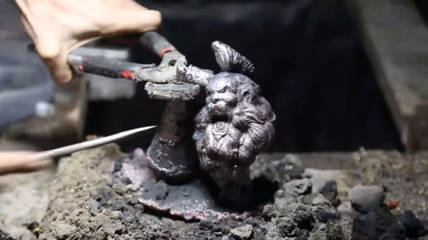
[BackyardScientist] obtained his metal by hunting the local thrift stores. He used the “lost foam” method of casting, by carving a sword out of styrofoam. The sword was embedded in a 5 gallon bucket of sand with a riser to allow the mold to be filled. The pewter was melted on a cheap hot plate, and poured into the mold. The hot metal melts the foam on contact, simultaneously filling up the cavity left over in the sand mold. [BackyardScientist] was left with a solid pewter sword. It won’t hold an edge, but it is a great illustration of the technique.

Click past the break to see [TheBackyardScientist’s] video.

Continue reading “From Scrap To Sword: Casting Pewter”

Pen Gun

Pneumatic Pen Gun Is Fit For James Bond

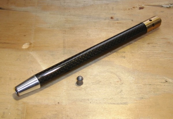
The James Bond franchise is well-known for many things, but perhaps most important to us hackers are the gadgets. Bond always had an awesome gadget that somehow was exactly the thing he needed to get out of a jam. [hw97karbine’s] latest project would fit right into an old Bond flick. He’s managed to build a single-shot pellet gun that looks like a pen.

[hw97karbine] started out by cutting the body from a tube of carbon fiber. He used a hacksaw to do the cutting, and then cleaned up the edges on a lathe. A barrel was cut from a piece of brass tubing with a smaller diameter. These two tubes will eventually sit one inside of the other. A custom front end cap was machined from brass. One end is ribbed and glued into the carbon fiber tube. The barrel is also glued to this end of the front cap, though it’s glued to the inside of the cap. The other end of the cap has 1/8″ BSP threads cut into it in order to allow for attachments.

A rear end cap is machined from Delrin. This piece also has a Delrin piston placed inside. The piston has a small piece of rubber used as a gasket. This piston valve is what allows the gun to operate. The rear cap gets glued into place and attached to a Schrader valve, removed from an automotive tire valve stem.

To pressurize the system, a bicycle pump is attached to the Schrader valve. This pushes the piston up against the barrel, preventing any of the air from escaping. The piston doesn’t make a perfect seal, so air leaks around it and pressurizes the carbon fiber tube. The Schrader valve prevents the air from leaking out of the pen body. A special machined button was threaded onto the Schrader valve. When the button is pressed, the air escapes; the sudden pressure imbalance causes the piston to shoot backwards, opening up a path for the air to escape through the barrel. This escaping air launches the projectile. The whole process is explained better with an animation.

Now, the question left in our mind: is this the same pressure imbalance concept that was used in that vacuum pressure bazooka we saw a couple years back?

Continue reading “Pneumatic Pen Gun Is Fit For James Bond”

Horn Antenna

Building A Horn Antenna For Radar

So you’ve built yourself an awesome radar system but it’s not performing as well as you had hoped. You assume this may have something to do with the tin cans you are using for antennas. The obvious next step is to design and build a horn antenna spec’d to work for your radar system. [Henrik] did exactly this as a way to improve upon his frequency modulated continuous wave radar system.

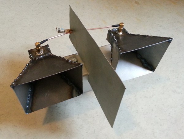
To start out, [Henrik] designed the antenna using CST software, an electromagnetic simulation program intended for this type of work. His final design consists of a horn shape with a 100mm x 85mm aperture and a length of 90mm. The software simulation showed an expected gain of 14.4dB and a beam width of 35 degrees. His old cantennas only had about 6dB with a width of around 100 degrees.

The two-dimensional components of the antenna were all cut from sheet metal. These pieces were then welded together. [Henrik] admits that his precision may be off by as much as 2mm in some cases, which will affect the performance of the antenna. A sheet of metal was also placed between the two horns in order to reduce coupling between the antennas.

[Henrik] tested his new antenna in a local football field. He found that his real life antenna did not perform quite as well as the simulation. He was able to achieve about 10dB gain with a field width of 44 degrees. It’s still a vast improvement over the cantenna design.

If you haven’t given Radar a whirl yet, check out [Greg Charvat’s] words of encouragement and then dive right in!

unicycle

Offset Unicycle Built Mostly From A Single Bicycle

[Lou’s] friends all said that it would be impossible to build a unicycle that had offset pedals. Moving the pedals to the front of the unicycle would throw off the balance and prevent the user from being able to ride it. [Lou] proved them wrong using mostly components from a single donor bicycle.

The donor bike gets chopped up into a much smaller version of itself. The pedals stay attached in the original location and end up being out in front of the rider. The seat is moved backwards, which is the key to this build. Having the rider’s legs out in front requires that there be a counter balance in back. Moving the seat backwards gets the job done with relative ease.

To prevent the hub from free wheeling, [Lou] lashes the sprocket directly to the wheel spokes using some baling wire. He also had to remove the derailer and shorted the chain. All of this gives the pedals a direct connection to the wheel, allowing for more control. The video does a great job explaining the build quickly and efficiently. It makes it look easy enough for anyone to try. Of course, actually riding the unicycle is a different matter. Continue reading “Offset Unicycle Built Mostly From A Single Bicycle”

Printing In Metal With A MIG Welder

Whenever the question of metal 3D printers comes up, someone always chimes in that a MIG welder connected to a normal 3D printer would work great. A bit of research would tell this person that’s already been done, but some confirmation and replication is nice. A few students at TU Delft University strapped a welder to a normal, off-the-shelf 3D printer and made a few simple shapes.

This project builds on the work of [Joshua Pearce] et al. at Michigan Tech where an MIG welder and delta bot was used to lay down rather complex shapes on a metal plate substrate. The team at TU Delft used a cartesian bot – a Prusa i3 – for their replication because of the sheer mass of moving a metal build plate, firebricks, and welder around.

In the first few prints on their machine, the team was able to lay down enough metal to build a vertical wall. It’s not much, and to turn this into a finished part would require some machining, but these are only the beginning steps of what could become a legitimate way of creating metal parts. Video below.

Continue reading “Printing In Metal With A MIG Welder”