We’ve all been there. You’re building up a microcontroller project and you wish that you could just add “one more feature” but you’re limited by the hardware. Time to start thinking. (Or, arguably, buy the next model up.)
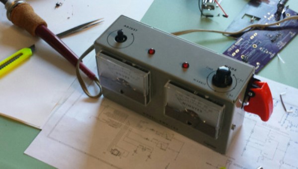
[Sam Feller] found himself in this position, adding a knob to set the time and a button to arm the alarm for his Analog Voltmeter Clock, and he came up with a way to implement an on-off switch, and poll a button and a potentiometer with only two pins of a microcontroller.
The problem with potentiometers in low-power designs is that they’re always leaking power. That is, unless you switch them off when you’re not using them. So the ideal solution is to power the potentiometer from one GPIO pin on the microcontroller, and read its value with another. That’s two GPIO pins just for the potentiometer. But [Sam] needed to read input from a button too, and he was out of pins.


His clever solution is to switch two resistors in or out of the circuit depending on the status of the pushbutton, so that the voltage range at the potentiometer is between either VCC and VCC/2 when the switch is pressed, or between VCC/2 and GND when the switch is not pressed.
If the ADC reads something higher than VCC/2, the microcontroller knows that the button is pressed, and vice-versa. The potentiometer’s setting determines exactly where the voltage lies within either range.
Done and done. If you find yourself in the similar situation of needing to read in values from a whole bunch of buttons instead of a potentiometer, then you can try using an R-2R DAC wired up to the pushbuttons and reading the (analog) value to figure out which buttons are pressed. (If you squint your eyes just right, this solution is the same as the R-2R DAC one with the potentiometer replacing all but the most-significant bit of the R-2R DAC.)
Another tool for the toolbox. Thanks [Sam].