Amplifying The Body’s Own Electricity

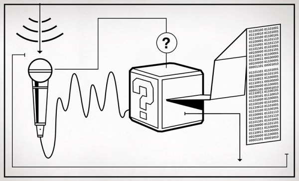
Measuring the body’s electrical signals is a neat trick… if you can get your equipment dialed in enough to establish dependable measurements. The technique is called Surface ElectroMyography (SEMG) though you’ll hear many call this ECG. They’re essentially the same technology; the Electro CardioGraph instruments monitor the activity of the heart while SEMG Instruments monitor electrical signals used to control other muscles. Both types of hardware amount to an instrumentation type amplifier and some form of I/O or display.

This topic has been in my back pocket for many months now. Back in May we Hackaday’ites descended on New York City for the Disrupt NY Hackathon event. We arrived a day or so early so that we might better peruse the Korean BBQ joints and check out the other electronics that NY has to offer. On Saturday we gathered around, each shouting out the size of his or her t-shirt preference as we covered up our black Hackaday logo tees with maroon maroon ones (sporting the Hackaday logo of course) for a 24-hour craze of hardware hacking.

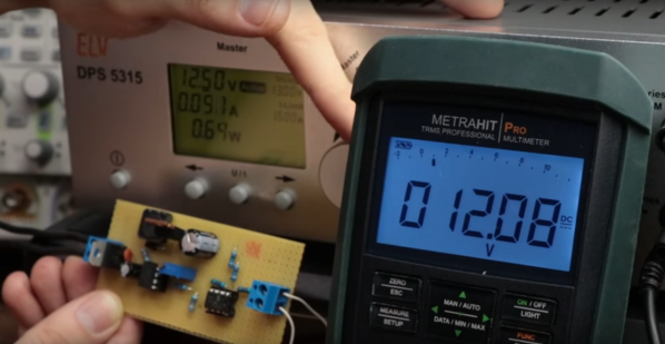
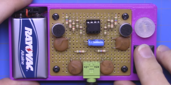
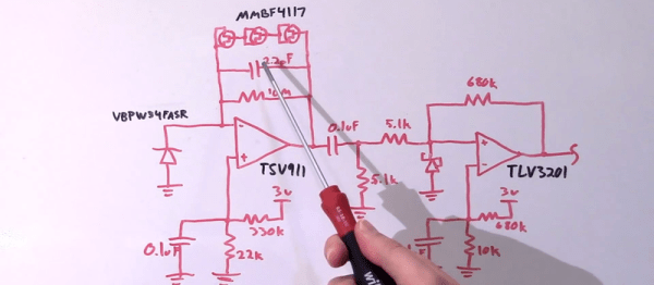
There were two individuals at our tables who were both hacking away on hardware to measure the electrical field produced by the body’s muscles in some form or another. The electrical signals measured from the skin are small, and need careful consideration to measure the signal despite the noise. This is a fun experiment that lets you work with both Instrumentation Amplifiers and OpAmps to achieve a usable signal from the movement of your body.

Continue reading “Amplifying The Body’s Own Electricity”

Hackaday Links: November 8, 2015

[Burt Rutan] is someone who needs no introduction. Apparently, he likes the look of the Icon A5 and is working on his own version.

Earlier this week, the US Air Force lost a few satellites a minute after launch from Barking Sands in Hawaii. This was the first launch of the three stage, solid fueled SPARK rocket, although earlier versions were used to launch nuclear warheads into space. There are some great Army videos for these nuclear explosions in space, by the way.

[Alexandre] is working on an Arduino compatible board that has an integrated GSM module and WiFi chip. It’s called the Red Dragon, and that means he needs some really good board art. The finished product looks good in Eagle, and something we can’t wait to see back from the board house.

The Chippocolypse! Or however you spell it! TI is declaring a lot of chips EOL, and although this includes a lot of op-amps and other analog ephemera (PDF), the hi-fi community is reeling and a lot of people are stocking up on their favorite amplifiers.

[Jeremy] got tired of plugging jumper wires into a breadboard when programming his ATMega8 (including the ‘168 and ‘328) microcontrollers. The solution? A breadboard backpack that fits right over the IC. All the files are available, and the PCB can be found on Upverter.

In case you haven’t heard, we’re having a Super Conference in San Francisco later this week. Adafruit was kind enough to plug our plug for the con on Ask an Engineer last week.

A Peek Under The Hood Of The 741 Op-Amp

First introduced as an IC back in 1968, but with roots that go back to 1941, the 741 has been tweaked and optimized over the years and is arguably the canonical op-amp. [Ken Shirriff] decided to take a look inside everybody’s favorite op-amp, and ended up with some good-looking photomicrographs and a lot of background on the chip.

canRather than risk the boiling acid method commonly used to decap epoxy-potted ICs, [Ken] wisely chose a TO-99 can format to attack with a hacksaw. With the die laid bare for his microscope, he was able to locate all the major components and show how each is implemented in silicon. Particularly fascinating is the difference between the construction of NPN and PNP transistors, and the concept of “current mirrors” as constant current sources. And he even whipped up a handy interactive chip viewer – click on something in the die image and find out which component it is on the 741 schematic. Very nice.

We’ve seen lots of chip decappings before, including this reveal of TTL and CMOS logic chips. It’s nice to see the guts of the venerable 741 on display, though, and [Ken]’s tour is both a great primer for the newbie and a solid review for the older hands. Don’t miss the little slice of history he included at the end of the post.

Scanning Electron Microscope Images And Animations Pulled By Impressive Teensy LC Setup

When you’ve got a scanning electron microscope sitting around, you’re going to find ways to push the awesome envelope. [Ben Krasnow] is upping his SEM game with a new rig to improve image capture (video link) and more easily create animated GIFs and videos.

The color scheme of the SEM housing gives away its 80s vintage, and the height of image capture technology back then was a Polaroid camera mounted over the instrument’s CRT. No other video output was provided, so [Ben] dug into the blueprints and probed around till he found the high-resolution slow scan signal.

To make his Teensy-LC happy, he used a few op-amps to condition the analog signal for the greatest resolution and split out the digital sync signals, which he fed into the analog and digital ports respectively. [Ben] then goes into a great deal of useful detail on how he got the video data encoded and sent over USB for frame capture and GIF generation. Reading the ADC quickly without jitter and balancing data collection with transmission were tricky, but he has established a rock-solid system for it.

Continue reading “Scanning Electron Microscope Images And Animations Pulled By Impressive Teensy LC Setup”

How To Build A Thermocouple Amplifier

A Thermocouple is a terrific way to measure temperature. The effects of temperature change on dissimilar metals produces a measurable voltage. But to make that measurement you need an amplifier circuit designed for the thermocouple being used.

Linear Technology LTC 1049 Low Power Zero-Drift Operational Amplifier with Internal Capacitors
Linear Technology LTC 1049 Low Power Zero-Drift Operational Amplifier
with Internal Capacitors

While researching “Zero Drift Amplifiers” as a follow-up to my video on Instrumentation Amplifiers I noticed the little schematic the front page of the LTC1049 datasheet which is shown here. I thought it was an ideal example of an analog application where some gain and some “gain helper” were needed to accomplish our useful little application of amplifying a thermocouple probe.

In the video I don’t really talk much about the thermocouples themselves other than the type I see most of the time which is type K. If you’re not already familiar with the construction of these probes you can find an informative write-up on thermocouples and the different types on the Wikipedia page and you might also want to check out the Analog Devices app note if you would like to know more. What I will cover is a reliable and precise way to read from these probes, seen in the video below and the remainder of the post after the break.

Continue reading “How To Build A Thermocouple Amplifier”

The Modular Bench Power Supply To Rule Them All

Right now, [The Big One] is using an ATX power supply as a bench power supply for all his electronics projects. It works, but it’s not ideal. The next step up from a power supply from an old computer is, in order, one of those Chinese deals on Amazon, a used HP supply, or for the very cool people among us, building your own. [The Big One] is very, very cool and he’s building the modular bench supply to rule them all.

This is not your $100 china special power supply that [The Big One] would have to buy again in a few months. Inside this massive power supply is a massive transformer and rectifier that fans out to multiple power supply modules. The modules themselves will be based on an OPA548 that will be able to supply up to 3A with current limiting.

Each of these channels will be controlled by an ATMega32u4, with all the fancy stuff you’d expect from the ultimate supply; USB for setting voltage, current, and logging data, a nice LCD character display, and it’s surprisingly cheap; just about $100 for the transformer, and about $50 for each module.

It’s shaping up to be a great build, and with all the features, a power supply that would also make a great kit. If you have any input you’d like [The Big One] to hear, let him know on the project page.

Bil Herd: Computing With Analog

When I was young the first “computer” I ever owned was an analog computer built from a kit. It had a sloped plastic case which had three knobs with large numerical scales around them and a small center-null meter. To operate it I would dial in two numbers as indicated by the scales and then adjust the “answer” by rotating the third dial until the little meter centered. Underneath there was a small handful of components wired on a terminal strip including two or three transistors.

In thinking back about that relic from the early 1970’s there was a moment when I assumed they may have been using the transistors as logarithmic amplifiers meaning that it was able to multiply electronically. After a few minutes of thought I came to the conclusion that it was probably much simpler and was most likely a Wheatstone Bridge. That doesn’t mean it couldn’t multiply, it was probably the printed scales that were logarithmic, much like a slide rule.

Did someone just ask what a slide rule was? Let me explain further for anyone under 50. If you watch the video footage or movies about the Apollo Space Program you won’t see any anyone carrying a hand calculator, they didn’t exist yet. Yet the navigation guys in the first row of Mission Control known aptly as “the trench”, could quickly calculate a position or vector to within a couple of decimal places, and they did it using sliding piece of bamboo or aluminum with numbers printed on them.

Continue reading “Bil Herd: Computing With Analog”