It’s the little touches that make a project, and a nice nameplate can really tie a retro build together. Such badges are easy enough to make with a CNC machine, but if you don’t have access to machine tools you can put chemistry to work for you with these acid-etched brass nameplates.
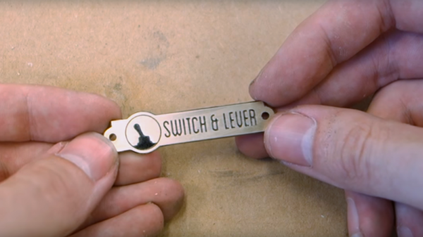
The etching method that [Switch and Lever] uses to get down to brass plaques will be intimately familiar to anyone who has etched a PCB before. Ferric chloride works as well on brass as it does on copper, and [Switch and Lever] does a good job explaining the chemistry of the etching process and offers some tips on making up etching solution from powdered ferric chloride. But the meat of the video below is the head-to-head test of three different masking methods.
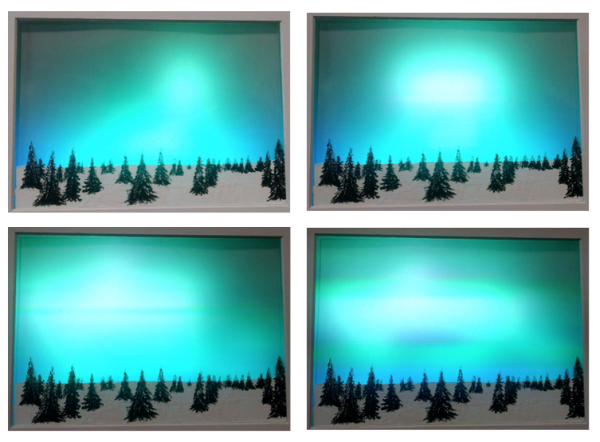
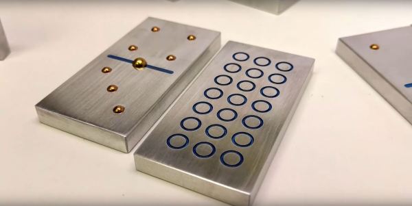
The first method uses a laser printer and glossy paper ripped from a magazine to create a mask. The toner is transferred to the brass using an office laminator, and the paper removed with gentle rubbing before etching. For the other two candidates he uses a laser engraver to remove a mask of plain black spray paint in one case, or to convert special laser marking paint to a mask in the other.
We won’t spoil the surprise as to which gave the best results, but we think you’ll be pleased with how easy making classy nameplates can be. You can also use electrolytic methods for a deeper etch, but we think acid etching is a little more approachable for occasional use.
Continue reading “Three Ways To Etch Snazzy Brass Nameplates”
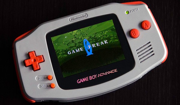
 The buttons were not as easy as the shell. [Michael] originally decided casting would be the best solution, but after multiple attempts, he couldn’t get the color right. Even with opaque dyes in the resin, the buttons would still come out slightly translucent. In the end, [Michael] decided to paint the original buttons.