There was a time when the very idea of building a complex circuit with the intention of destroying it would have been anathema to any electrical engineer. The work put into designing a circuit, procuring the components, and assembling it, generally with point-to-point wiring and an extravagant amount of manual labor, only to blow it up? Heresy!
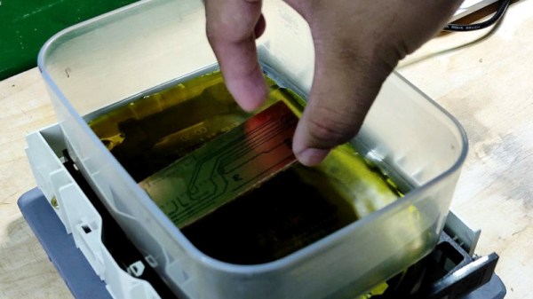
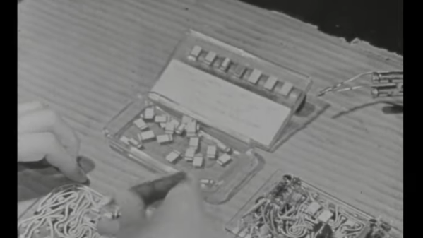
But, such are the demands of national defense, and as weapons morphed into “weapon systems” after World War II, the need arose for electronics that were not only cheap enough to blow up but also tough enough to survive the often rough ride before the final bang. The short film below, simply titled “Potted and Printed Circuits“, details the state of the art in miniaturization and modularization of electronics, circa 1952. It was produced by the Telecommunications Research Establishment (TRE), the main electronics R&D entity in the UK during the war which was responsible for inventions such as radar, radio navigation, and jamming technology.
Continue reading “Retrotechtacular: Circuit Potting, And PCBs The Hard Way”