[Matt] created an animated gif of New Horizon’s Pluto flyby. The source images were taken from the the raw LORRI images, modified so the background star field could be seen, and assembled with OpenCV. Because Pluto and Charon orbit each other around a point above Pluto’s surface, simply putting Pluto in the center of each frame wouldn’t work. It’s the best visual explanation of this weird arrangement yet, all brought to you by the magic of OpenCV and Python.
On the subject of Kickstarter creators that don’t understand the conservation of energy, I present this.
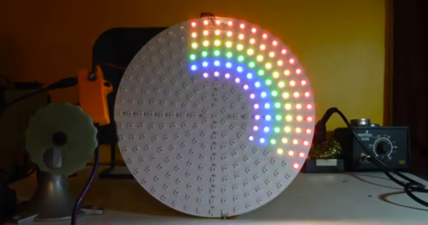
We don’t know exactly what’s going on with this one, but here’s a swimming pool covered with RGB LEDs. It’s controlled by two Rainbowduinos, and looks like the coolest disco floor you’ve ever seen.
[Frank]’s 2011 Hundai Santa Fe wasn’t cool enough, so he added an F16 flight stick to his shift knob. The choice of joystick is paramount here: Saitek joysticks look too techy, Logitech ones are too expensive, and the Warthog H.O.T.A.S costs $400. Joysticks are extremely niche peripherals these days, it seems. He ended up strapping an old F16 joystick from the 90s on his shift knob, and it looks close enough to the real thing.
Two bodgers are stuffing the engine from a Toyota Celica into a 1980 Mini, and they’re trying to make it look stock. We’ve seen their project before, and now there’s a new episode. In this episode: the pedal box, the steering wheel, and figuring out how to make the car drive straight.