Headlight Mod For An Audi A3

If you have a car that is getting on in years, it may be missing some of the latest frills and features that the latest models sport. [Muris] has a slightly dated Audi A3 8P which did not have an AUTO setting for the headlights. In the newer models, this feature turns on the headlights when the ambient light falls below a threshold level (overcast conditions or when going through a tunnel), or when the windshield wipers are turned on. The light sensor is integrated behind the rear view mirror in a special mount, requiring an expensive windshield upgrade if he were to opt for the factory retrofit. Instead, he decided to build his own Automatic Headlights Sensor upgrade for his Audi A3.

His local regulations require the car headlights to be on all the time when the vehicle is in motion. So adding this feature may seem moot at first sight. But [Muris] programmed the headlights to be powered at 70% during daytime conditions and switch to 100% when his sensor detects low ambient light conditions. In the power save mode, all of the other non-essential lights (number plate, tail light) are also turned off to hopefully extend their life. He achieved this by using the VCDS (VAG-COM Diagnostic System) – a widely used aftermarket diagnostics tool for VW-Audi Group vehicles. His tiny circuit switches the lights between the two power settings.

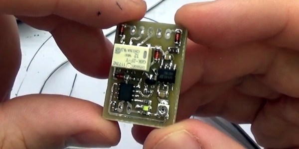
His plan was to install the device without disturbing the original wiring or light switch assembly in any way. The low-powered device consists of a PIC micro-controller, an LDR (light dependent resistor) for light sensing and a low current relay which switches between the two modes. Setting the threshold at which the circuit switches the output is adjusted by a variable trimpot acting as a voltage divider with the LDR. [Muris] wired up a short custom harness which let him install this circuit between the default light switch and the car electronics. After switching on power, he has 15 seconds to enable or disable his unit by toggling the light switch five times, and that status gets stored in memory. The tiny board is assembled using SMD parts and is protected with a heatshrink sleeve. The circuit would work equally well with a lot of other cars, so If you’ve got one which could do with this feature upgrade, then [Muris] has the Eagle CAD files and code available for download on his blog.

Check out the video below where he runs a demo, describes his circuit in detail and then proceeds to assemble the PCB without using a vise or a third hand to hold the PCB. That’s a fancy watch he’s sporting at 00:50 s down the video.

Continue reading “Headlight Mod For An Audi A3”

Underwater distributed sensor network

Open Source Underwater Distributed Sensor Network

One way to design an underwater monitoring device is to take inspiration from nature and emulate an underwater creature. [Michael Barton-Sweeney] is making devices in the shape of, and functioning somewhat like, clams for his open source underwater distributed sensor network.

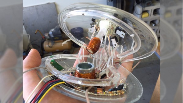
Underwater distributed sensor network descent and ascentThe clams contain the electronics, sensors, and means of descending and ascending within their shells. A bunch of them are dropped overboard on the surface. Their shells open, allowing the gas within to escape and they sink. As they descend they sample the water. When they reach the bottom, gas fills a bladder and they ascend back to the surface with their data where they’re collected in a net.

Thus far he’s made a few clams using acrylic for the shells which he’s blown himself. He soldered the electronics together free-form and gave them a conformal coating of epoxy. He’s also used a thermistor as a stand-in for other sensors and is already working on a saturometer, used for measuring the total dissolved gas (TDG) in the water. Knowing the TDG is useful for understanding and mitigating supersaturation of water which can lead to fish kills.

He’s also given a lot of thought into the materials used since some clams may not make it back up and would have to degrade or be benign where they rest. For example, he’s been using a lithium battery for now but would like to use copper on one shell and zinc on another to make a salt water battery, if he can make it produce enough power. He’s also considering using 3D printing since PLA is biodegradable. However, straight PLA could be subject to fouling by underwater organisms and would require cleaning, which would be time-consuming. PLA becomes soft when heated in a dishwasher and so he’s been looking into a PLA and calcium carbonate filament instead.

Check out his hackaday.io page where he talks about all these and more issues and feel free to make any suggestions.

Robot Radar Module

For his Hackaday Prize entry, [Ted Yapo] is building a Robot Radar Module breakout board. His design uses the A111 60 GHz pulsed coherent radar (PCR) sensor from Acconeer AB (New Part alert!) .

The A111 is a low power, high precision sensor ideal for use in object detection or gesture sensing applications. The BGA package is tiny – 5.5 mm x 5.2 mm, but it does not appear very difficult for a hacker to assemble. The sensor includes an integrated baseband, RF front-end and Antenna in Package so you don’t have to mess with RF layout headaches. Acconeer claims the sensor performance is not affected with interference from noise, dust, color and direct or indirect light. Sensing range is about 2 m with a +/- 2 mm accuracy. And at just under $10 a pop for 10 units or more, it would make a nice addition to augment the sensor package on a Robot.

To get started, [Ted] is keeping his design simple and small – the break out board measures just 32 mm x 32 mm. The radar sensor itself doesn’t require any parts other than a crystal and its loading capacitors. A LDO takes care of the 1.8 V required by the A111. Three 74LVC2T45 chips translate the SPI digital interface from 1.8 V to external logic levels between 1.8 V to 5 V. The three level translation chips could possible be replaced by a single six or eight channel translator – such as one from the TXB series from TI. For his first PCB iteration, [Ted] is expecting to run in to some layout or performance issues, so if you have any feedback to give him on his design, check out his hardware repository on Github.

Acconeer provides a Getting Started guide for their Evaluation Kits, which includes a detailed Raspberry-Pi / Raspbian installation and an accompanying video (embedded after the break) targeted at hackers. We are eagerly looking forward to the progress that [Ted] makes with this sensor breakout. Combined with LiDAR ToF sensor breakout boards, such as the MappyDot, it would be a great addition to your robot’s sensing capabilities.

Continue reading “Robot Radar Module”

Color-Coded Key Opens Doors, Opportunities

Of all the ways to open up a lock, there are some tried and true methods. Keys, combinations, RFIDs, picks, and explosives have all had their time and place, but now someone else wants to try something new. [Erik] has come up with a lock that opens when it is shown a pattern of colors.

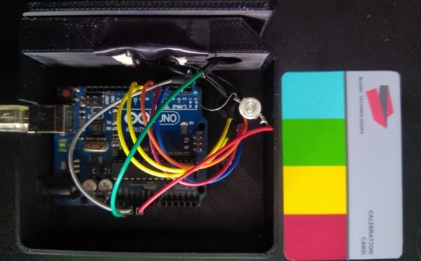
The lock in question uses a set of color coded cards as the “keys”. When the cards are inserted in the lock, a TCS230 color sensor interprets the pattern on the cards and sends the information over to an Arduino Uno. From there, the Arduino can command the physical lock to open if the pattern is a match, although [Erik] is still waiting on the locking mechanism to arrive while he continues to prototype the device.

This is a fairly unique idea with a number of upsides. First, the code can’t be “stolen” from inside a wallet like RFID cards can. (Although if you can take a picture of the card all bets are off.) If you lose your key, you can simply print another one, and the device is able to handle multiple different keys and log the usage of each one. Additionally, no specialized equipment is needed to create the cards, unlike technologies that rely on magnetic strips. Of course, there’s always this classic way of opening doors if you’d rather go old school with your home locks.

Continue reading “Color-Coded Key Opens Doors, Opportunities”

What’s Inside A Neonode Laser Sensor?

Every once in a while, you get your hands on a cool piece of hardware, and of course, it’s your first instinct to open it up and see how it works, right? Maybe see if it can be coaxed into doing just a little bit more than it says on the box? And so it was last Wednesday, when I was at the Embedded World trade fair, and stumbled on a cool touch display floating apparently in mid-air.

The display itself was a sort of focused Pepper’s Ghost illusion, reflected off of an expensive mirror made by Aska3D. I don’t know much more — I didn’t get to bring home one of the fancy glass plates — but it looked pretty good. But this display was interactive: you could touch the floating 2D projection as if it were actually there, and the software would respond. What was doing the touch response in mid-air? I’m a sucker for sensors, so I started asking questions and left with a small box of prototype Neonode zForce AIR sensor sticks to take apart.
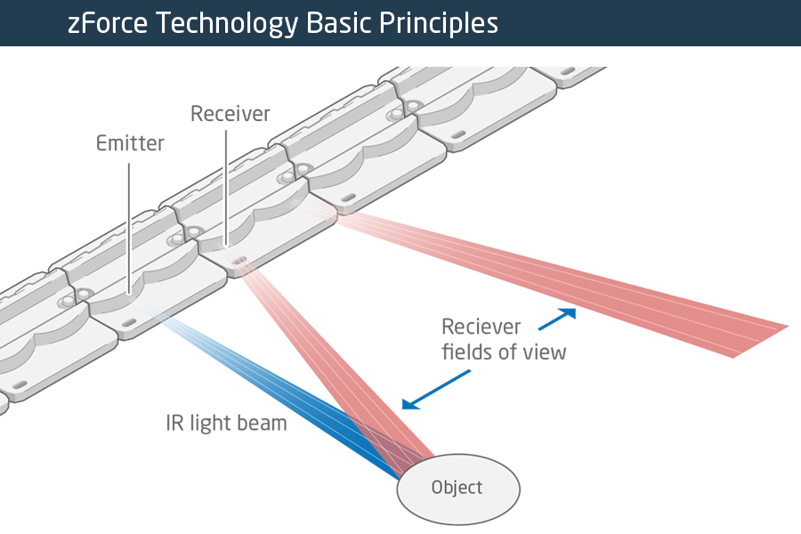
The zForce sensors are essentially an array of IR lasers and photodiodes with some lenses that limit their field of view. The IR light hits your finger and bounces back to the photodiodes on the bar. Because the photodiodes have a limited angle over which they respond, they can be used to triangulate the distance of the finger above the display. Scanning quickly among the IR lasers and noting which photodiodes receive a reflection can locate a few fingertips in a 2D space, which explained the interactive part of the floating display. With one of these sensors, you can add a 2D touch surface to anything. It’s like an invisible laser harp that can also sense distance.

The intended purpose is fingertip detection, and that’s what the firmware is good at, but it must also be the case that it could detect the shape of arbitrary (concave) objects within its range, and that was going to be my hack. I got 90% of the way there in one night, thanks to affordable tools and free software that every hardware hacker should have in their toolbox. So read on for the unfortunate destruction of nice hardware, a tour through some useful command-line hardware-hacking tools, and gratuitous creation of animations from sniffed SPI-like data pulled off of some test points.

Continue reading “What’s Inside A Neonode Laser Sensor?”

This Radio Gets Pour Reception

When was the last time you poured water onto your radio to turn it on?

Designed collaboratively by [Tore Knudsen], [Simone Okholm Hansen] and [Victor Permild], Pour Reception seeks to challenge what constitutes an interface, and how elements of play can create a new experience for a relatively everyday object.

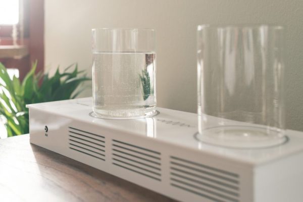
Lacking buttons or knobs of any kind, Pour Reception appears an inert acrylic box with two glasses resting on top. A detachable instruction card cues the need for water, and pouring some into the glasses wakes the radio.

Continue reading “This Radio Gets Pour Reception”

Heated DryBox Banishes Filament Moisture For Under $20

There has been a lot of activity from [Richard Horne] regarding 3D printing filaments lately; most recently he has shared two useful designs for upping one’s filament storage and monitoring game. The first is for a DIY Heated DryBox for 3D printing filament. It keeps filament dry not just by sealing it into a plastic box with some desiccant, but by incorporating a mild and economical heater intended for reptile habitats inside. Desiccant is great, but a gently heated enclosure can do wonders for driving away humidity in the right environment. The DryBox design also incorporates a handy little temperature and humidity sensor to show how well things are working.

Spool-mounted adapter for temperature and humidity sensor (and desiccant) to monitor storage bag conditions.

The second design is a simple spin-off that we particularly liked: a 3D printed adapter that provides a way to conveniently mount one of the simple temperature and humidity sensors to a filament spool with a desiccant packet. This allows storing a filament spool in a clear plastic bag as usual, but provides a tidy way to monitor the conditions inside the bag at a glance. The designs for everything are on Thingiverse along with the parts for the Heated DryBox itself.

[Richard] kindly shares the magic words to search for on eBay for those seeking the build’s inexpensive key components: “15*28CM Adjustable Temperature Reptile Heating Heater Mat” and “Mini LCD Celsius Digital Thermometer Hygrometer Temperature Humidity Meter Gauge”. There are many vendors selling what are essentially the same parts with minor variations.

Since the DryBox is for dispensing filament as well as storing it, a good spool mounting system is necessary but [Richard] found that the lack of spool standardization made designing a reliable system difficult. He noted that having spool edges roll on bearings is a pretty good solution, but only if one doesn’t intend to use cardboard-sided spools, otherwise it creates troublesome cardboard fluff. In the end, [Richard] went with a fixed stand and 3D printable adapters for the spools themselves. He explains it all in the video, embedded below.

Continue reading “Heated DryBox Banishes Filament Moisture For Under $20”