When you’re soldering, smoke rises from your iron. That smoke is full of a variety of chemicals, depending on what type of solder you’re using, but it’s almost certainly not good for you. That’s why you can buy fume extractors to suck smoke away.
But benchtop extractors tend to suck, and not in the way they’re supposed to. It can be hard to get the extractor to pick up all the fumes, leaving fumes that float into your face.
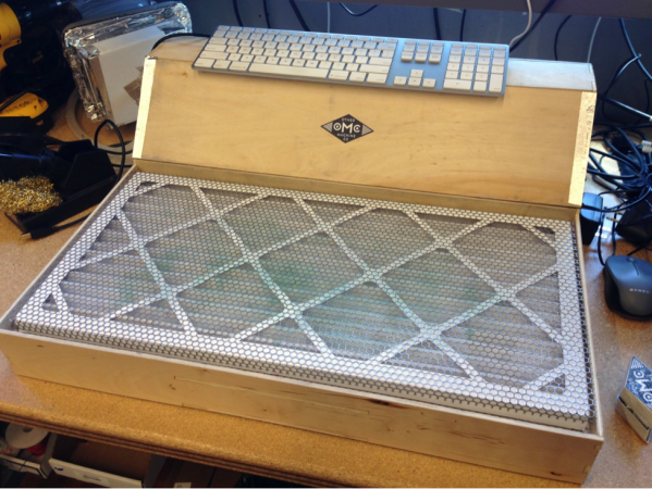
Over at Other Machine Co., they built up a custom downdraft fume extractor to solve this problem. The downdraft extractor is a table that you work on, providing downwards suction that grabs the fumes. Their table uses a standard MERV13 air filter that’s rated to trap particles as small as 1.0–0.3 μm. Cooling fans provide the airflow, and a piece of perforated sheet metal acts as a work surface.
The table works great for soldering, and is also helpful for working with other chemicals like adhesives and solvents. DXF files for the frame parts are provided, and everything else can be sourced from McMaster.