Making Prints More Resilient With Fibre-Filled Filament

For all that we love 3D printers, sometimes the final print doesn’t turn out as durable as we might want it to be.

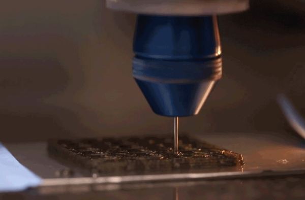
Aiming to mimic the properties of natural structures such as wood, bone, and shells, a research team lead by [Jennifer A. Lewis] at Harvard John A. Paulson School of Engineering and Applied Sciences’ Lewis Lab have developed a new combined filament and printing technique which they call rotational 3D printing.

Minuscule fibres are mixed in with the epoxy filament and their controlled orientation within the print can reinforce the overall structure or specific points that will undergo constant stresses. To do so the print head is fitted with a stepper motor, and its precisely programmed spin controls the weaving of the fibres into the print. The team suggests that they would be able to adapt this tech to many different 3D printing methods and materials, as well as use different materials and printed patterns to focus on thermal, electrical, or optical properties.

Be it adding carbon nano-tubes or enlisting the expertise of spiders to refine our printed materials, we’re looking forward to the future of ever stronger prints. However, that doesn’t mean that existing methods are entirely lacking in endurance.

[Thanks for the tip, Qes!]
Smooth stepper motor robot arm

Stepper Motor Robot Arm Has Smooth Moves

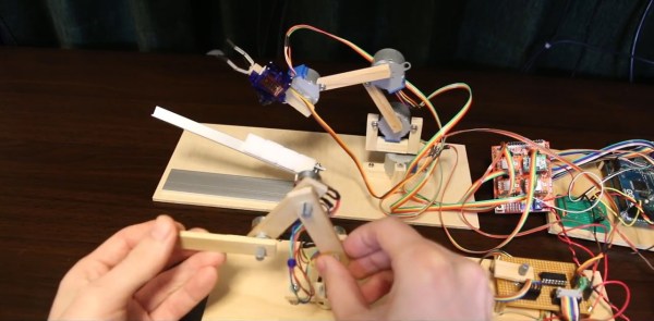
[Tobias Kuhn] had watched a YouTube video about a robot arm which used servo motors, and wanted to try making one himself. But he found it hard to get slow or smooth movements out of the servos. Even removing the microcontroller and trying to work with the servo’s driver-IC and potentiometer from an Arduino Nano didn’t get him satisfaction.

Then he found the very affordable 28BYJ-48 stepper motor. After some experimenting, he came up with a smooth moving robot arm with four steppers controlled from an Arduino Mega and A4988 stepper motor drivers. Rather than write a bunch of stepper motor code himself, he installed and ran a four-axis fork of grbl on the Arduino, turning it into a stepper motor controller. One minor hitch was that the A4988 motor drivers are for bipolar stepper motors but 28BYJ-48 steppers are unipolar. Luckily he knew of a very simple hack which our [Brian Benchoff] wrote about for turning a unipolar motor into a bipolar motor.

To tell the robot arm what to do, he built a replica arm with potentiometers in place of the stepper motors. As he manipulates the replica, the values of the potentiometers are read by a Raspberry Pi and some custom Python code which sends the appropriate G-code to the Arduino/grbl controlled robot arm. There’s a bit of a lag but when he moves the replica arm, the robot arm does the same move. See it in action in the video below.

Continue reading “Stepper Motor Robot Arm Has Smooth Moves”

Man-in-the-Middle Jog Pendant: Two Parts Make Easier Dev Work

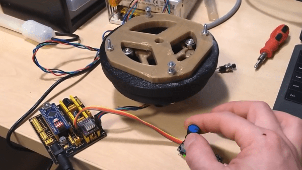
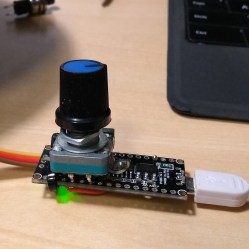
In a project, repetitive tasks that break the flow of development work are incredibly tiresome and even simple automation can make a world of difference. [Simon Merrett] ran into exactly this while testing different stepper motors in a strain-wave gear project. The system that drives the motor accepts G-Code, but he got fed up with the overhead needed just to make a stepper rotate for a bit on demand. His solution? A grbl man-in-the-middle jog pendant that consists of not much more than a rotary encoder and an Arduino Nano. The unit dutifully passes through any commands received from a host controller, but if the encoder knob is turned it sends custom G-Code allowing [Simon] to dial in a bit acceleration-controlled motor rotation on demand. A brief demo video is below, which gives an idea of how much easier it is to focus on the nuts-and-bolts end of hardware when some simple motor movement is just a knob twist away.
Continue reading “Man-in-the-Middle Jog Pendant: Two Parts Make Easier Dev Work”

Touch-A-Sketch Gives An Old Toy A New Twist

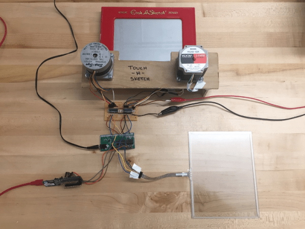
After nearly 60 years and a lot of stairs and squares, there is finally an easier way to draw on an Etch A Sketch®. For their final project in embedded microcontroller class, [Serena, Francis, and Alejandro] implemented a motor-driven solution that takes input from a touch screen.

Curves are a breeze to draw with a stylus instead of joysticks, but it’s still a 2-D plotter and must be treated as such. The Touch-A-Sketch system relies on the toy’s stylus starting in the lower left hand corner, so all masterpieces must begin at (0,0) on the knobs and the touch screen.

The BOM for this project is minimal. A PIC32 collects the input coordinates from the touch screen and sends them to a pair of stepper motors attached to the toy’s knobs. Each motor is driven by a Darlington array that quickly required a homemade heat sink, so there’s even a hack within the hack. The team was unable to source couplers that could deal with the discrepancy between the motor and knob shaft sizes, so they ended up mounting the motors in a small plywood table and attaching them to the stock knobs with Velcro. This worked out for the better, since the Etch A Sketch® screen still has to be reset the old-fashioned way.

They also considered using belts to drive the knobs like this clock we saw a few years ago, but they wanted to circumvent slippage. Pour another glass of your aunt’s high-octane eggnog and watch Touch-A-Sketch draw something festive after the break.

Continue reading “Touch-A-Sketch Gives An Old Toy A New Twist”

OpenBraille Is An Impressive DIY Embosser

In 2024, the Braille system will have been around for 200 years. What better way to mark the occasion than with an open source project devoted to making embossing equipment affordable for the visually impaired? This long overdue cause became the plight of [ccampos7], who couldn’t find a DIY embosser kit and set out to build one himself.

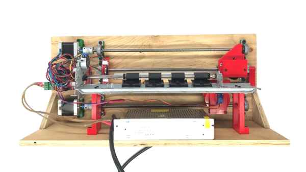
While other embossers forcibly punch the letters in one go, OpenBraille takes a more gradual approach to ensure a clean impression with a rolling motion. Paper is placed between a mechanical encoder with moving pins and a dimpled roller that provides resistance and a place to land. The embossing head is driven by an Arduino Mega and a standard RAMPS board, as the rest of the system relies on Cartesian movement.

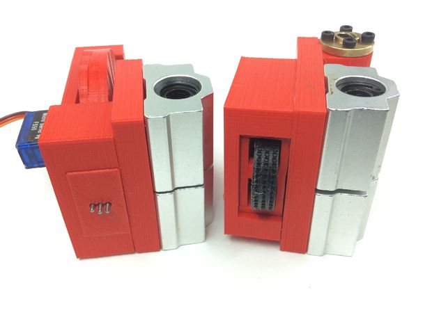
The encoder and roller.

The encoder mechanism itself is pretty interesting. A micro servo drives a 3D printed wheel with three distinct tracks around half of the edge. The peaks and valleys encoded in these plastic tracks actuate the embossing pins, which are made from nails embedded through the sides of hex nuts. There’s a quick demo of the encoder movement after the break, and another video of it in action on the OpenBraille Facebook page.

[ccampos7] has all the files up on Thingiverse and plans to post the software soon. You should also check out this compact embosser that was recognized in the first round of the 2017 Hackaday Prize which is a nice all-print Braille concept. Continue reading “OpenBraille Is An Impressive DIY Embosser”

Stepper Driver Module With Swappable Heatsinks

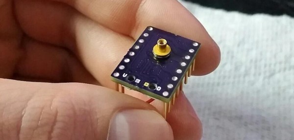
At first glance, [Dean Gouramanis]’s stepper driver module for 3D printers looks like just another RAMPS-compatible stepper board. Except, what could that gold-plated copper peg sticking out of the PCB possibly be? That would be [Dean]’s PowerPeg Thermal Management System that he built and entered in the Hackaday Prize competition for 2015, where it rocked its way into the Finals. It’s a thermal connector peg that attaches to a variety of heatsinks so you can swap in whatever sink fits the bill.

In the case of this project, [Dean] created a custom PCB that accommodates the PowerPeg connector, onto which the heat sink screws. Needless to say, he machined his own heatsinks to go with the pegs, though it looks like you could use any sink with enough surface contact that can be secured by the same #0-80 screw.

You shouldn’t be surprised that hackers obsess over heatsinks. This heatsink tester project we published helps determine which sink  to use. Another post gives all the ins and outs of ordering a custom heatsink.

This DIY Turntable Just Got Freaky Fresh

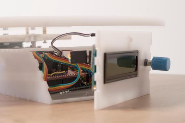
Photography turntables are made for both the precise and lazy. Whether you are concerned about the precision of consistent angles during a photo shoot or you simply do not want to stand there rotating a plate after every picture — yes, it does get old — a lazy susan style automatic photography turntable is the ticket. This automatic 360° design made over at circuito.io satisfies both of these needs in an understated package

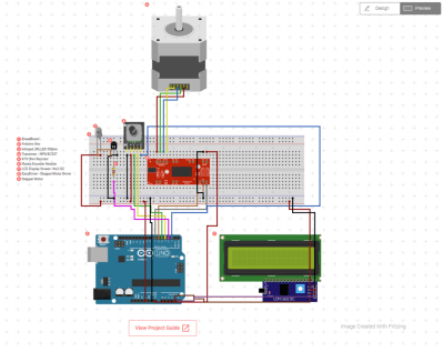
The parts required to make this DIY weekend project are about as minimal as they get. An Arduino Uno controls it all with a rotary encoder for input and a character LCD to display settings. The turntable moves using a stepper motor and an EasyDriver. It even takes care of controlling the camera using an IR LED.

The biggest obstruction most likely to arise is creating the actual laser cut casing itself. The circuito team avoided this difficulty by using Pololu‘s online custom laser cutting service for the 4 necessary laser cut parts. After all of the components have been brought together, all that is left to do is Avengers assemble. They provide step by step instructions for this process in such a straightforward way that you could probably put this sucker together blindfolded.

We have seen some other inspired photography turntables on Hackaday before. [NotionSunday] created a true turntable hack based off of the eject mechanism of an old DVD-ROM drive. With the whole thing spinning on the head assembly of a VCR, this is the epitome of letting nothing go to waste. We also displayed another very similar Arduino Uno controlled turntable created 2 years ago by [Tiffany Tseng]. There is even a non-electronic version out there of a DIY 360° photography turntable that only uses a lazy susan and tape measure. All of these photography turntable hacks do the job wonderfully, but there was something that we liked about the clean feel of this one. All of the necessary code for this project has been provided over at GitHub. What is your favorite photography turntable?