We are fantastically lucky not only in the parts that are easily available to us at reasonable cost, but also for the affordable test equipment that we can have on our benches. It was not always this way though, and [NFM] treats us to an extensive teardown and upgrade of a piece of test equipment from the days when a hacker’s bench would have been well-appointed with just a multimeter and a 10MHz ‘scope.
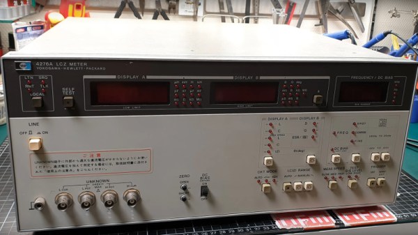
The Hewlett Packard 4276A LCZ meter is, or perhaps was, the king of component testers. A 19″ rack unit that would comfortably fill a shelf, it has a host of functions and a brace of red LED displays. This particular meter had clearly seen better days, and required a look inside just to clean up connectors and replace aged batteries.
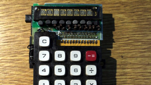
In the case is a backplane board with a series of edge connectors for a PSU, CPU, and analogue boards. Aged capacitors and those batteries were replaced, and those edge connectors cleaned up again. The CPU board appears to have a Z80 at its heart, and we’re sure we spotted a 1987 date code. There are plenty of nice high-quality touches, such as the individual 7-segment digits being socketed.
An after-market option for this equipment included a DC offset board, and incredibly HP publish its full schematic and a picture of its PCB in their manual. It was thus a simple process and quick PCB ordering to knock up a modern replica, with just a few component substitutions and single resistors replacing an HP specific encapsulated resistor pack.
As a treat we get a ringside seat for the set-up and alignment of the machine. The DC offset board gives the wrong voltage, which he traces to a voltage reference with a different tolerance to the original HP part. [NFM] makes some adjustments to resistor values, and is able to pull the voltage to the correct value. Finally we see the instrument put through its paces, and along the way have a demonstration of how capacitance of a ceramic capacitor can vary with voltage close to its working voltage. Even if you never have the need for an LCZ meter or never see an HP 4276A, this should be worth a watch. And if you now have an urge to find a bench full of similar treasures, take a look at our guide to old test equipment.