Automate The Freight: Shipping Containers Sorted By Robot Stevedores

Towering behemoths are prowling the docks of Auckland, New Zealand, in a neverending shuffle of shipping containers, stacking and unstacking them like so many out-sized LEGO bricks. And they’re doing it all without human guidance.
It’s hard to overstate the impact containerized cargo has had on the modern world. The ability to load and unload ships laden with containers of standardized sizes rapidly with cranes, and then being able to plunk those boxes down onto a truck chassis or railcar carrier for land transportation has been a boon to the world’s economy, and it’s one of the main reasons we can order electronic doo-dads from China and have them show up at our doors essentially for free. At least eventually.
As with anything, solving one problem often creates other problems, and containerization is no different. The advantages of being able to load and unload one container rather than separately handling the dozen or more pallets that can fit inside it are obvious. But what then does one do with a dozen enormous containers? Or hundreds of them?
That’s where these giant self-driving cranes come in, and as we’ll see in this installment of “Automate the Freight”, these autonomous stevedores are helping ports milk as much value as possible out of containerization.

Continue reading “Automate The Freight: Shipping Containers Sorted By Robot Stevedores”

Fail Of The Week: How Not To Make A 3D Scanner

Sometimes the best you can say about a project is, “Nice start.” That’s the case for this as-yet awful DIY 3D scanner, which can serve both as a launching point for further development and a lesson in what not to do.

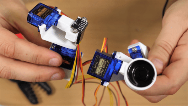
Don’t get us wrong, we have plenty of respect for [bitluni] and for the fact that he posts his failures as well as his successes, like composite video and AM radio signals from an ESP32. He used an ESP8266 in this project, which actually uses two different sensors: an ultrasonic transducer, and a small time-of-flight laser chip. Each was mounted to a two-axis scanner built from hobby servos and 3D-printed parts. The pitch and yaw axes move the sensors through a hemisphere gathering data, but unfortunately, the Wemos D1 Mini lacks the RAM to render the complete point cloud from the raw points. That’s farmed out to a WebGL page. Initial results with the ultrasonic sensor were not great, and the TOF sensor left everything to be desired too. But [bitluni] stuck with it, and got a few results that at least make it look like he’s heading in the right direction.

We expect he’ll get this sorted out and come back with some better results, but in the meantime, we applaud his willingness to post this so that we can all benefit from his pain. He might want to check out the results from this polished and pricey LIDAR scanner for inspiration.

Continue reading “Fail Of The Week: How Not To Make A 3D Scanner”

XLIDAR Is A Merry-Go-Round Of Time-Of-Flight Sensors

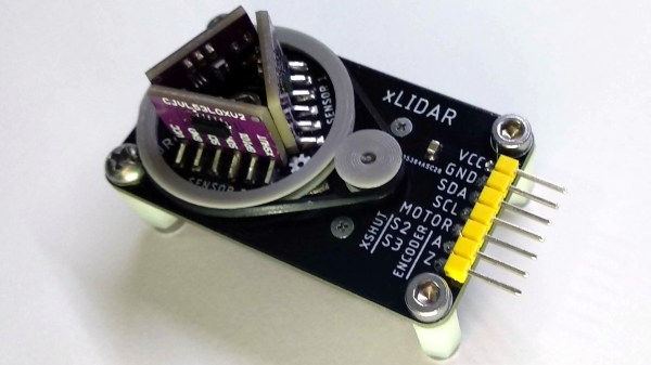
[JRodrigo]’s xLIDAR project is one of those ideas that seemed so attractively workable that it went directly to a PCB prototype without doing much stopping along the way. The concept was to mount a trio of outward-facing VL53L0X distance sensors to a small PCB disk, and then turn that disk with a motor and belt while taking readings. As the sensors turn, their distance readings can be used to paint a picture of the immediate surroundings (at least within about 1 meter, which is the maximum range of the VL53L0X.)

The hardware is made to be accessible and has a strong element of “what you see is what you get.” The distance sensors are on small breakout boards, and the board turns the sensor disk via a DC motor and 3D printed belt drive. Even the method of encoding the disk’s movement and zero position has the same WYSIWYG straightforwardness: a spring contact and an interrupted bare copper trace on the bottom of the sensor disk acts as a physical switch. In fact, exposed copper traces in concentric circular patterns and spring pins taken from an SD card socket are what provide power and communications as the disk turns.

The prototype looks good and sounds like it should work, but how well does it hold up? We’ll find out once [JRodrigo] does some testing. Until then, the board designs are available on the project’s GitHub repository if anyone wants to take a shot at their own approach without starting from scratch.

Roll Up Your Sleeve, Watch A Video With This Smart Watch Forearm Projector

We’re all slowly getting used to the idea of wearable technology, fabulous flops like the creepy Google Glass notwithstanding. But the big problem with tiny tech is in finding the real estate for user interfaces. Sure, we can make it tiny, but human fingers aren’t getting any smaller, and eyeballs can only resolve so much fine detail.

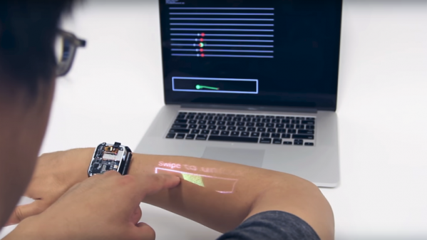
So how do we make wearables more usable? According to Carnegie-Mellon researcher [Chris Harrison], one way is to turn the wearer into the display and the input device (PDF link). More specifically, his LumiWatch projects a touch-responsive display onto the forearm of the wearer. The video below is pretty slick with some obvious CGI “artist’s rendition” displays up front. But even the somewhat limited displays shown later in the video are pretty impressive. The watch can claim up to 40-cm² of the user’s forearm for display, even at the shallow projection angle offered by a watch bezel only slightly above the arm — quite a feat given the irregular surface of the skin. It accomplishes this with a “pico-projector” consisting of red, blue, and green lasers and a pair of MEMS mirrors. The projector can adjust the linearity and brightness of the display to provide a consistent image across the uneven surface. An array of 10 time-of-flight sensors takes care of watching the display area for touch input gestures. It’s a fascinating project with a lot of potential, but we wonder how the variability of the human body might confound the display. Not to mention the need for short sleeves year round.

Need some basics on the micro-electrical mechanic systems (MEMS) behind the pico-projector in this watch? We’ve got a great primer on these microscopic machines.

Continue reading “Roll Up Your Sleeve, Watch A Video With This Smart Watch Forearm Projector”

Touchless Shop Doors Over-Engineered To A Blissful Level

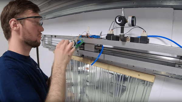
When [John Saunders] wanted an automatic door for his shop, rather than settle for a commercial unit, he designed and built a proximity-sensing opener to ease his passing. Sounds simple, right?

Fortunately for us, there are no half-measures at Saunders Machine Works, thanks to the multiple Tormach workcells and the people who know how to use them. The video below treats us to quite a build as a result; the first part is heavy on machining the many parts for the opener, so skip ahead to 8:33 if you’re more interested in the control electronics and programming.

The opener uses time-of-flight distance sensors and an Arduino to detect someone approaching, with a pneumatic cylinder to part a plastic strip curtain. [John] admits to more than a little scope creep with this one, which is understandable when you’ve got easy access to the tools needed to create specialized parts at will.

In the end, though, it works well for everyone but [Judd], the shop dog, and it certainly looks like it was a fun build to boot. [John]’s enthusiasm for mixing machining and electronics is infectious; check out his automated bowl feeder for assembly line use.

Continue reading “Touchless Shop Doors Over-Engineered To A Blissful Level”

Hackaday Prize Entry: MappyDot, A Micro Smart LiDAR Sensor

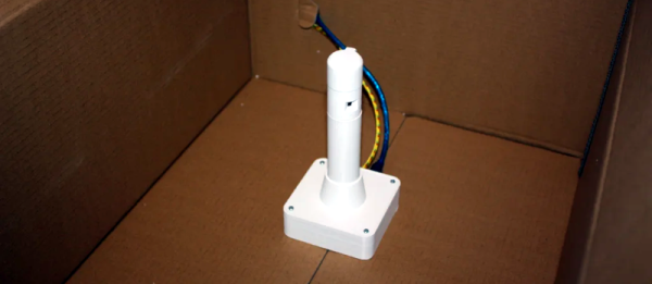
[Blecky]’s entry to the Hackaday Prize is MappyDot, a tiny board less than a square inch in size that holds a VL53L0X time-of-flight distance sensor and can measure distances of up to 2 meters.

MappyDot is more than just a breakout board; the ATMega328PB microcontroller on each PCB provides filtering, an easy to use  I2C interface, and automatically handles up to 112 boards connected in a bus. The idea is that one or a few MappyDots can be used by themselves, but managing a large number is just as easy. By dotting a device with multiple MappyDots pointing in different directions, a device could combine the readings to gain a LiDAR-like understanding of its physical environment. Its big numbers of MappyDots [Blecky] is going for, too: he just received a few panels of bare PCBs that he’ll soon be laboriously populating. The good news is, there aren’t that many components on each board.

It’s great to see open sourced projects and tools in which it is clear some thought has gone into making them flexible and easy to use. This means they are easier to incorporate into other work and helps make them a great contestant for the Hackaday Prize.

Measuring Air Flow With Ultrasonic Sensors

Measuring air flow in an HVAC duct can be a tricky business. Paddle wheel and turbine flow meters introduce not only resistance but maintenance issue due to accumulated dust and debris. Being able to measure ducted airflow cheaply and non-intrusively, like with this ultrasonic flow meter, could be a big deal for DIY projects and the trades in general.

The principle behind the sensor [ItMightBeWorse] is working on is nothing new. He discovered a paper from 2015 that describes the method that measures the change in time-of-flight of an ultrasonic pulse across a moving stream of air in a duct. It’s another one of those “Why didn’t I think of that?” things that makes perfect sense in theory, but takes some engineering to turn into a functional sensor. [ItMightBeWorse] is using readily available HC-SR04 sensor boards and has already done a proof-of-concept build. He’s getting real numbers back and getting close to a sensor that will go into an HVAC automation project. The video below shows his progress to date and hints at a follow-up video with more results soon.

Here’s wishing [ItMightBeWorse] the best of luck with his build. But if things go sideways, he might look to our post-mortem of a failed magnetic flow meter for inspiration.

Continue reading “Measuring Air Flow With Ultrasonic Sensors”