A New Wrinkle On Wooden Ribbon Microphones

Not too many people build their own microphones, and those who do usually build them out of materials like plastic and metal. [Frank Olson] not only loves to make microphones, but he’s also got a thing about making them from wood, with some pretty stunning results.

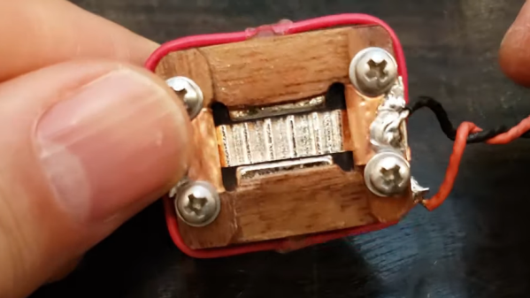
[Frank]’s latest build is a sorta-kinda replica of the RCA BK-5, a classic of mid-century design. Both the original and [Frank]’s homage are ribbon microphones, in which a thin strip of corrugated metal suspended between the poles of magnets acts as a transducer. But the similarities end there, as [Frank] uses stacked layers of walnut veneer as the frame of his ribbon motor. The wood pieces are cut with a vinyl cutter, stacked up, and glued into a monolithic structure using lots of cyanoacrylate glue. The video below makes it seem easy, but we can imagine getting everything stacked neatly and lined up correctly is a chore, especially when dealing with neodymium magnets. Cutting and corrugating the aluminum foil ribbon is no mean feat either, nor is properly tensioning it and making a solid electrical contact.

The ribbon motor is suspended in a case made of yet more wood, all of which contributes to a warm, rich sound. The voice-over for the whole video below was recorded on a pair of these mics, and we think it sounds just as good as [Frank]’s earlier wooden Model 44 build. He says he has more designs in the works, and we’re looking forward to hearing them, too. Continue reading “A New Wrinkle On Wooden Ribbon Microphones”

Solving Grounding Issues On Switch Audio

Grounding of electrical systems is an often forgotten yet important design consideration. Issues with proper grounding can be complicated, confusing, and downright frustrating to solve. So much so that engineers can spend their entire careers specializing in grounding and bonding. [Bsilvereagle] was running into just this sort of frustrating problem while attempting to send audio from a Nintendo Switch into a PC, and documented some of the ways he attempted to fix a common problem known as a ground loop.

Ground loops occur when there are multiple paths to ground, especially in wires carrying signals. The low impedance path creates oscillations and ringing which is especially problematic for audio. When sending the Switch audio into a computer a loop like this formed. [Bsilvereagle] set about solving the issue using an isolating transformer. It took a few revisions, but eventually they settled on a circuit which improved sound quality tremendously. With that out of the way, the task of mixing the Switch audio with sources from other devices could finally proceed unimpeded.

As an investigation into a nuisance problem, this project goes into quite a bit of depth about ground loops and carrying signals over various transforming devices. It’s a great read if you’ve ever been stumped by a mysterious noise in a project. If you’ve never heard of a ground loop before, take a look at this guide to we featured a few years ago.

RoboTray Is A Secret Tea Butler

How far would you go for your cup of tea? [samsungite]’s missus doesn’t like clutter on her countertops, so away the one-cup kettle would go back into the cupboard for next time while the tea steeped. As long as there’s room for it in there, why not install it there permanently? That’s the idea behind RoboTray, which would only be cooler if it could be plumbed somehow.

RoboTray went through a few iterations, most importantly the switch from 6mm MDF to 4 mm aluminum plate. A transformer acts as a current sensor, and when the kettle is powered on, the tray first advances forward 7 cm using a 12 VDC motor and an Arduino. Then it pivots 90° on a lazy Susan driven by another 12 VDC motor. The kettle is smart enough to turn itself off when finished, and the Arduino senses this and reverses all the steps after a ten-second warning period. Check it out in action after the break.

If [samsungite] has any more Arduinos lying around, he might appreciate this tea inventory tracker.

Continue reading “RoboTray Is A Secret Tea Butler”

Measuring current draw of home shop tools

Using Homebrew Coils To Measure Mains Current, And Taking The Circuit Breaker Challenge

Like many hackers, [Matthias Wandel] has a penchant for measuring the world around him, and quantifying the goings-on in his home is a bit of a hobby. And so when it came time to sense the current flowing in the wires of his house, he did what any of us would do: he built his own current sensing system.

What’s that you say? Any sane hacker would buy something like a Kill-a-Watt meter, or even perhaps use commercially available current transformers? Perhaps, but then one wouldn’t exactly be hacking, would one? [Matthias] opted to roll his own sensors for quite practical reasons: commercial meters don’t quite have the response time to catch the start-up spikes he was interested in seeing, and clamp-on current transformers require splitting the jacket on the nonmetallic cabling used in most residential wiring — doing so tends to run afoul of building codes. So his sensors were simply coils of wire shaped to fit the outside of the NM cable, with a bit of filtering to provide a cleaner signal in the high-noise environment of a lot of switch-mode power supplies.

Fed through an ADC board into a Raspberry Pi, [Matthias]’ sensor system did a surprisingly good job of catching the start-up surge of some tools around the shop. That led to the entertaining “Circuit Breaker Challenge” part of the video below, wherein we learn just what it really takes to pop the breaker on a 15-Amp branch circuit. Spoiler alert: it’s a lot.

Speaking of staying safe with mains current, we’ve covered a little bit about how circuit protection works before. If you need a deeper dive into circuit breakers, we’ve got that too.

Continue reading “Using Homebrew Coils To Measure Mains Current, And Taking The Circuit Breaker Challenge”

Custom Isolated Variac Is Truly One Of A Kind

It’s no surprise that many hardware hackers avoid working with AC, and frankly, we can’t blame them. The potential consequences of making a mistake when working with mains voltages are far greater than anything that can happen when you’re fiddling with a 3.3 V circuit. But if you do ever find yourself leaning towards the sparky side, you’d be wise to outfit your bench with the appropriate equipment.

Take for example this absolutely gorgeous variable isolation transformer built by [Lajt]. It might look like a  high-end piece of professional test equipment, but as the extensive write-up and build photographs can attest, this is a completely custom job. The downside is that this particular machine will probably never be duplicated, especially given the fact its isolation transformer was built on commission by a local company, but at least we can look at it and dream.

This device combines two functions which are particularly useful when repairing or testing AC hardware. As a variable transformer, often referred to as a variac, it lets [Lajt] select how much voltage is passed through to the output side. There’s a school of thought that says slowly ramping up the voltage when testing an older or potentially damaged device is better than simply plugging it into the wall and hoping for the best. Or if you’re like Eddie Van Halen, you can use it to control the volume of your over-sized Marshall amplifiers when playing in bars.

Image of the device's internal components.Secondly, the unit isolates the output side. That way if you manage to cross the wrong wire, you’re not going to pop a breaker and plunge your workshop into darkness. It also prevents you from accidentally blowing up any AC powered test equipment you might employ while poking around, such as that expensive oscilloscope, since the devices won’t share a common ground.

Additional safety features have been implemented using an Arduino Uno R3 clone, a current sensor, and several relays. The system will automatically cut off power to the device under test should the current hit a predetermined threshold, and will refuse to re-enable the main relay until the issue has been resolved. The code has been written in such a way that whenever the user makes a configuration change, power will be cut and must be reestablished manually; giving the user ample time to decide if its really what they want to do.

[Lajt] makes it clear that the write-up isn’t meant as a tutorial for building your own, but that shouldn’t stop you from reading through it and getting some ideas. Whether you’re in the market for custom variac tips or just want to get inspired by an impeccably well engineered piece of equipment, this project is a high-water mark for sure.

Flat Transformer Gives This PCB Tesla Coil Some Kick

Arguably, the most tedious part of any Tesla coil build is winding the transformer. Getting that fine wire wound onto a suitable form, making everything neat, and making sure it’s electrically and mechanically sound can be tricky, and it’s a make-or-break proposition, both in terms of the function and the aesthetics of the final product. So this high-output printed circuit Tesla should take away some of that tedium and uncertainty.

Now, PCB coils are nothing new — we’ve seen plenty of examples used for everything from motors to speakers. We’ve even seen a few PCB Tesla coils, but as [Ray Ring] points out, these have mostly been lower-output coils that fail to bring the heat, as it were. His printed coil generates some pretty serious streamers — a foot long (30 cm) in some cases. The secondary of the coil has 6-mil traces spaced 6 mils apart, for a total of 240 turns. The primary is a single 240-mil trace on the other side of the board, and the whole thing is potted in a clear, two-part epoxy resin to prevent arcing. Driven by the non-resonant half-bridge driver living on the PCB below it, the coil can really pack a punch. A complete schematic and build info can be found in the link above, while the video below shows off just what it can do.

Honestly, for the amount of work the PCB coil saves, we’re tempted to give this a try. It might not have the classic good looks of a hand-wound coil, but it certainly gets the job done. Continue reading “Flat Transformer Gives This PCB Tesla Coil Some Kick”

Keep Coffee Warm Through Induction Heating

Transformers have an obvious use for increasing or decreasing the voltage in AC systems, but they have many other esoteric uses as well. Electric motors and generators are functionally similar and can be modeled as if they are transformers, but the truly interesting applications are outside these industrial settings. Wireless charging is essentially an air-core transformer that allows power to flow through otherwise empty space, and induction cooking uses a similar principle to induce current flow in pots and pans. And, in this case, coffee mugs.

[Sajjad]’s project is an effort to keep his coffee warm while it sits on his desk. To build this special transformer he places his mug inside a coil of thick wire which is connected to a square wave generator. A capacitor sits in parallel with the coil of wire which allows the device to achieve resonance at a specific tuned frequency. Once at that frequency, the coil of wire efficiently generates eddy currents in the metal part of the coffee mug and heats the coffee with a minimum of input energy.

While this project doesn’t work for ceramic mugs, [Sajjad] does demonstrate it with a metal spoon in the mug. While it doesn’t heat up to levels high enough to melt solder, it works to keep coffee warm in a pinch if a metal mug isn’t available. He also plans to upgrade it so it takes up slightly less space on his desk. For now, though, it can easily keep his mug of coffee hot while it sits on his test bench.

Continue reading “Keep Coffee Warm Through Induction Heating”