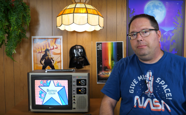
Keeping older technology working becomes exponentially difficult with age. Most of us have experienced capacitor plague, disintegrating wire insulation, planned obsolescence, or even the original company failing and not offering parts or service anymore. To keep an antique running often requires plenty of spare parts, or in the case of [Aaron]’s vintage ’70s Sony television set, plenty of modern technology made to look like it belongs in a machine from half a century ago.
The original flyback transformer on this TV was the original cause for the failure of this machine, and getting a new one would require essentially destroying a working set, so this was a perfect candidate for a resto-mod without upsetting any purists. To start, [Aaron] ordered a LCD with controls (and a remote) that would nearly fit the existing bezel, and then set about integrating the modern controls with the old analog dials on the TV. This meant using plenty of rotary encoders and programming a microcontroller to do the translating.
There are plenty of other fine details in this build, including audio integration, adding modern video and audio inputs like HDMI, and adding LEDs to backlight the original (and now working) UHF and VHF channel indicators. In his ’70s-themed display wall, this TV set looks perfectly natural. If your own display wall spotlights an even older era, take a look at some restorations of old radios instead.
If you’ve laid hands on a retro analog TV, have the restoration bug, and you plan to make the final project at least somewhat period-correct, you face a bit of a conundrum: what are you going to watch? Sure, you can serve up just about any content digitally these days, but some programs just don’t feel right on an old TV. And even if you do get suitably retro programming, streaming isn’t quite the same as the experience of tuning your way through the somewhat meager selections as we did back in the analog days.
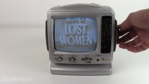
But don’t worry — this Raspberry Pi TV simulator can make your streaming experience just like the analog TV experience of yore. It comes to us from [Rodrigo], who found a slightly abused 5″ black-and-white portable TV that was just right for the modification. The battery compartment underneath the set made the perfect place to mount a Pi, which takes care of streaming a variety of old movies and shorts. The position of the original tuning potentiometer is read by an Arduino, which tells the Pi which “channel” you’re currently tuned to.
Composite video is fed from the Pi’s output right into the TV’s video input, and the image quality is just about what you’d expect. But for our money, the thing that really sells this is the use of a relay to switch the TV’s tuner back into the circuit for a short bit between channel changes. This gives a realistic burst of static and snow, just like we endured in the old days. Hats off to [Rodrigo] for capturing everything that was awful about TV back in the day — Mesa of Lost Women, indeed! — but still managing to make it look good.
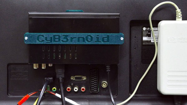
When we all shifted our television broadcasts to digital, for a moment it looked as though we might have had to upgrade our sets only once and a set-top box would be a thing of the past. In Europe that meant the DVB-T standard, whose two-decade reign is slowly passing to DVB-T2 for higher definition and more channels. All of this might seem simple but for the DVB-T2 standard being a transport layer alone without a specified codec. Thus the first generation of DVB-T2 equipment uses MPEG4 or H.264, while for some countries the most recent broadcasts use HEVC, or H.265. [CyB3rn0id] is there to guide us through the resulting mess, and along the way produce a nifty upgrade that integrates a set-top box on the back of an older DVB-T set.
Simply bolting a set-top box to a TV is not the greatest of hacks, however this one takes matters a little further with a 3D printed bracket and an extension which brings the box’s IR receiver out to the front of the TV on a piece of prototyping board. Along with a laptop power supply plumbed directly into the TV, it gives new life into a set which might otherwise have been headed for landfill.
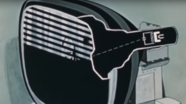
Watching television today is a very different experience from that which our parents would have had at our age, where we have high-definition digital on-demand streaming services they had a small number of analogue channels serving linear scheduled broadcasting. A particular film coming on TV could be a major event that it was not uncommon for most of the population to have shared, and such simple things as a coffee advert could become part of our common cultural experience. Behind it all was a minor miracle of synchronised analogue technology taking the signal from studio to living room, and this is the subject of a 1952 Coronet film, Television: How It Works! Sit back and enjoy a trip into a much simpler world in the video below the break.
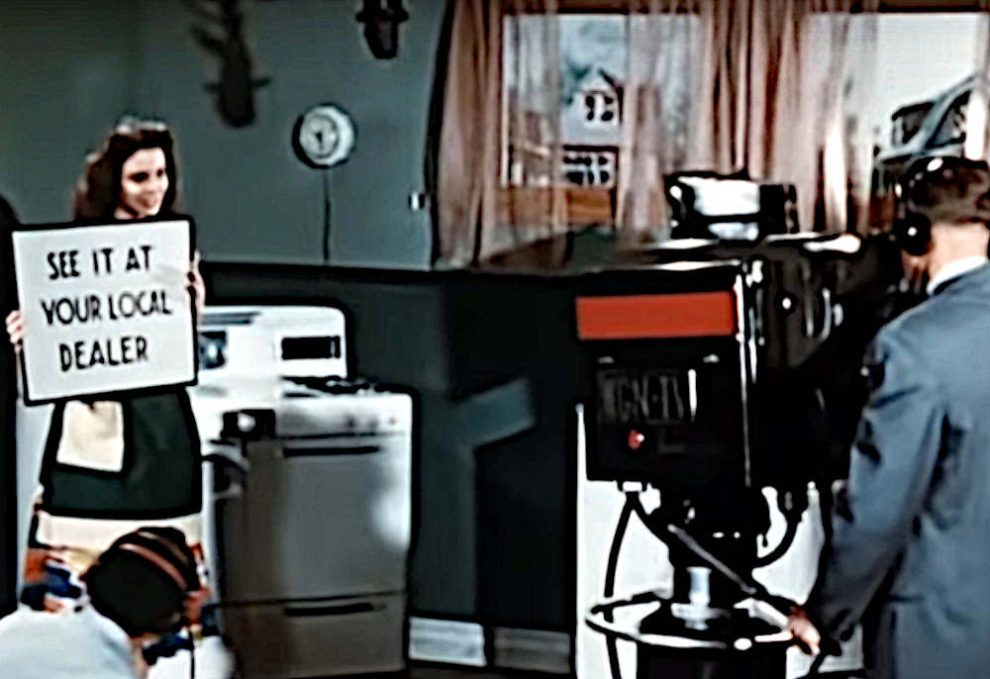
Production values for adverts had yet to reach their zenith in the 1950s.
After an introduction showing the cultural impact of TV in early-50s America there’s a basic intro to a cathode-ray tube, followed by something that may be less familiar to many readers, the Image Orthicon camera tube that formed the basis of most TV signals of that era.
It’s written for the general public, so the scanning raster of a TV image is introduced through the back-and-forth of reading a book, and then translated into how the raster is painted on the screen with the deflection coils and the electron gun. It’s not overly simplified though, for it talks about how the picture is interlaced and shows how a synchronisation pulse is introduced to keep all parts of the system working together.
A particularly fascinating glimpse comes in a brief mention of the solid copper co-axial cable and overland microwave links used to transmit TV signals across country, these concrete towers can still be seen today but they no longer have the colossal horn antennas we can see in the film.
A rather obvious omission in this film is the lack of any mention of colour TV, as while it would be late 1953 before the NTSC standard was formally adopted and early 1954 before the first few colour sets would go on sale. Colour TV would have been very much the Next Big Thing in 1952, but with no transmissions to watch and a bitter standards war still raging between the field-sequential CBS system and RCA’s compatible dot-sequential system that would eventually evolve into the NTSC standard it’s not surprising that colour TV was beyond the consumer audience of the time.
Thus we’re being introduced to the 525-line standard which many think of as NTSC video, but without the NTSC compatible colour system that most of us will be familiar with. The 525-line analogue standard might have disappeared from our living rooms some time ago, but as the last few stations only came off-air last year we’d say it had a pretty good run.
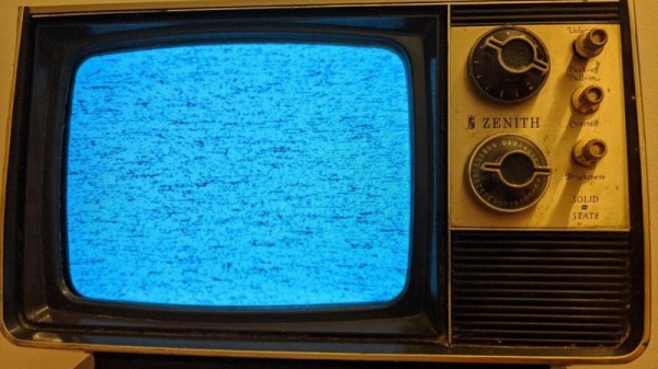
With the huge popularity of retrocomputing and of cyberdecks, we have seen a variety of projects that use a modern computer such as a Raspberry Pi bathed in the glorious glow of a CRT being used as a monitor. The right aesthetic is easily achieved this way, but there’s more to using a CRT display than simply thinking about its resolution. Particularly a black-and-white CRT or a vintage TV has some limitations due to its operation, that call for attention to the design of what is displayed upon it. [Jordan “Ploogle” Carroll] has taken a look at this subject, using a 1975 Zenith portable TV as an example.
The first difference between a flat panel and a CRT is that except in a few cases it has a curved surface and corners, and the edges of the scanned area protrude outside the edges of the screen. Thus the usable display area is less than the total display area, meaning that the action has to be concentrated away from the edges. Then there is the effect of a monochrome display on colour choice, in other words the luminance contrast between adjacent colours must be considered alongside the colour contrast. And finally there’s the restricted bandwidth of a CRT display, particularly when it fed via an RF antenna socket, which affects how much detail it can reasonably convey. The examples used are games, and it’s noticeable how Nintendo’s design language works well with this display. We can’t imagine Nintendo games being tested on black-and-white TV sets in 2022, so perhaps this is indicative of attention paid to design for accessibility.
While they require a bit of respect due to the presence of dangerous voltages, there’s a lot of fun to be had bringing a CRT into 2022. Get one while you still can, and maybe you could have a go at a retro cyberdeck.
84 years ago, a teenager built a TV set in a basement in Hammond, Indiana. The teen was a radio amateur, [John Anderson W9YEI], and since it was the late 1930s the set was a unique build — one of very few in existence built to catch one of the first experimental TV transmitters on air at the time, W9XZV in Chicago. We know about it because of its mention in a 1973 talk radio show, and because that gave a tantalizing description it’s caught the interest of [Bill Meara, N2CQR]. He’s tracking down whatever details he can find through a series of blog posts, and though he’s found a lot of fascinating stuff about early TV sets he’s making a plea for more. Any TV set in the late ’30s was worthy of note, so is there anyone else out there who has a story about this one?
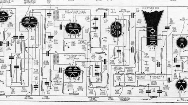
The set itself was described as an aluminium chassis with a tiny 1″ CRT, something which for a 1930s experimenter would have been an expensive and exotic part. He’s found details of a contemporary set published in a magazine, and looking at its circuit diagram we were immediately struck by how relatively simple the circuit of an electrostatically-deflected TV is. Its tuned radio frequency (TRF) radio front end is definitely archaic, but something that probably made some sense in 1939 when there was only a single channel to be received. We hope that [Bill] manages to turn up more information.
By our very nature, hackers tend to get on the bandwagon of new technology pretty quickly. When something gee-whiz comes along, it’s folks like us who try it out, even if that means climbing steep learning curves or putting together odd bits of technology rather than waiting for the slicker products that will come out if the new thing takes off. But building your own television receiver in 1933 was probably pushing the envelope for even the earliest of adopters.
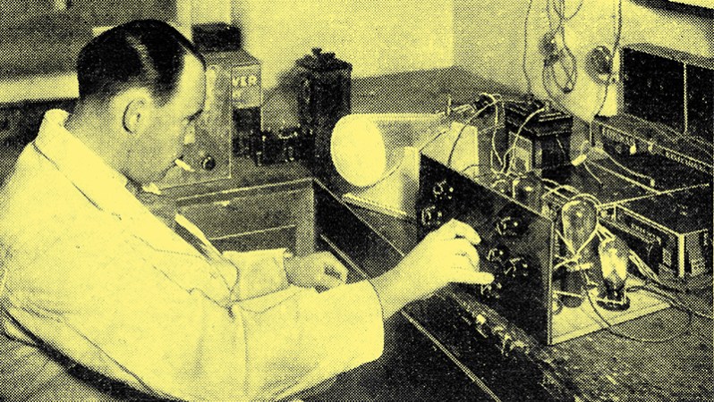
“Cathode Ray Television,” reprinted by the Antique Valve Museum in all its Web 1.0 glory, originally appeared in the May 27, 1933 edition of Popular Wireless magazine, and was authored by one K D Rogers of that august publication’s Research Department. They apparently took things quite seriously over there at the time, at least judging by the white lab coats and smoking materials; nothing said serious research in the 1930s quite like a pipe. The flowery language and endless superlatives that abound in the text are a giveaway, too; it’s hard to read without affecting a mental British accent, or at least your best attempt at a Transatlantic accent.
In any event, the article does a good job showing just what was involved in building a “vision radio receiver” and its supporting circuitry back in the day. K D Rogers goes into great detail explaining how an “oscillograph” CRT can be employed to display moving pictures, and how his proposed electronic system is vastly superior to the mechanical scanning systems that were being toyed with at the time. The build itself, vacuum tube-based though it was, went through the same sort of breadboarding process we still use today, progressing to a finished product in a nice wood cabinet, the plans for which are included.
It must have been quite a thrill for electronics experimenters back then to be working on something like television at a time when radio was only just getting to full market penetration. It’s a bit of a puzzle what these tinkerers would have tuned into with their DIY sets, though — the airwaves weren’t exactly overflowing with TV broadcasts in 1933. But still, someone had to go first, and so we tip our hats to the early adopters who figured things out for the rest of us.