Full Body VR Tracking Is Just Some Recycled Hardware Away

Full body tracking in VR applications involves attaching sensors to one’s body, and [Jaki] has a DIY method to do it on the cheap: the Vive Tracker Lite project repurposes Vive controllers as lighthouse-based trackers, no hardware modifications required.

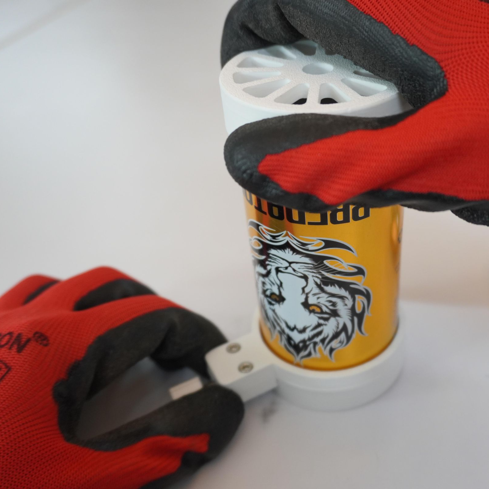
A common method of doing body tracking is to strap on some Vive trackers. Those are extremely hacker-friendly pieces of hardware, but [Jaki] observed that older Vive VR controllers can be had for cheap, and already contain everything a tracker needs. Some new firmware and a custom mount is all it takes to turn them into perfectly usable body trackers.

But what about a wireless receiver? [Jaki] has that covered as well with the $5 Viva Dongle, which uses a Pro Micro NRF52840 to act as a cheap DIY alternative to the official dongle hardware.

We appreciate the effort put into making this project accessible to everyone, even novices. [Jaki]’s put effort into a Python program with a full GUI to make the flashing of firmware as easy as possible for both projects. Experimenting with body tracking in VRChat or games with mods is just some recycled hardware away.

Granted, a Vive controller is not the slimmest piece of hardware, but all it takes is a firmware change and a 3D-printed fixture to make a perfectly serviceable tracker. That being said, we’re sure an enterprising hardware hacker may crack a controller open and embark on a serious rebuild, or even interface to some of the inputs in a clever way. If you’ve done that or know of someone who has, drop us a note on our tips line because we’d love to see it.

Voltmeter-Based Floating Point Calculator Does It In Style

[lcamtuf] is not just a calculator superfan, but also a skilled builder. That much is evident in the fabulous  design of Calcumator 2000, an electromechanical calculator that uses voltmeter readouts as digits (plus one at the bottom to represent decimal place). There are plenty of high-quality build images, so give it a look!

Meters like the one on the right (numbered 0 to 9) act as digit displays. The meter on the left indicates decimal position.

Calcumator 2000 is a bit of a love letter to a time when display technology hadn’t quite yet produced anything suitable for calculator use. This resulted in calculator designs that are generally unrecognizable compared to the 7-segment display based devices we see today. The Calcumator 2000, in all its electromechanical glory, would have fit right in that era.

The Calcumator 2000 has all the usual buttons one would expect from a simple calculator and drives a total of seven readouts, one of which acts as the decimal point. The idea of using voltmeters as digit displays came from [lcamtuf]’s voltmeter clock, an earlier work with a similar attention to detail in its design and assembly.

We want to take a moment to admire how clean the blue panel is. [lcamtuf] made it by painting one side of an acrylic panel, cutting the letters and design out on a CNC mill, then filling with white paint. The depth of the cuts gives the white elements a nifty multi-layer effect that really complements the design.

Want to see it work? Oh yes, you do. Check out the video, embedded just below.

Continue reading “Voltmeter-Based Floating Point Calculator Does It In Style”

DIY Steam Controller Puck Offers Xbox, Switch, PlayStation Emulation Modes

Valve recently released a new version of the Steam Controller, which features a wired USB puck that serves both as charger and dedicated, low-latency wireless receiver. The downside is they aren’t currently available for purchase separately, but that’s not a worry because you can now make your own thanks to [safijari]’s OpenPuck project.

OpenPuck uses the highly affordable Pro Micro NRF52840 board, programmed to emulate the wireless receiver portion of the puck, meaning one can pair their Steam Controller to it just like they would with the factory puck. A major part of the project was naturally documenting the wireless protocol, but there’s also an array of extra features offered by OpenPuck.

OpenPuck offers features over and above the factory offering. [image: 3d printed case by jaki-gh]
Hitting button combos lets one conveniently emulate Xbox, Nintendo Switch, or Sony PlayStation controllers. Meaning OpenPuck can for example be plugged into a Nintendo Switch and it will see OpenPuck as an official wired controller, complete with motion sensor and haptic feedback.

Why is it necessary for this emulation to be done from OpenPuck? Because while the Steam Controller has tight integration with Steam Input — a sort of highly useful translation layer for controller inputs — that integration also means the controller’s best features only work while Steam is running. OpenPuck’s ability to emulate other console controllers makes it flexible in a way the factory puck isn’t, and a user can make the most of a single controller this way.

It’s worth noting that while the real puck has the ability to charge the controller (whether or not the user makes it walk itself), the OpenPuck doesn’t have this ability. Does that mean one must still use the factory puck for charging? Not at all, as the Steam Controller charges just fine over a USB-C connection.

There’s a short video below that demonstrates the flashing and setup, so check it out if you think it might be useful to you.

Continue reading “DIY Steam Controller Puck Offers Xbox, Switch, PlayStation Emulation Modes”

Speak Silently With An Ultrasound Probe

Speaking is much faster than typing, and while it’s an increasingly convenient way to interact with computers, it’s hardly private. Providing speech privacy in a way we haven’t seen before is this prototype tongue-reading system that uses machine learning and ultrasound to read tongue movements and turn them into decoded speech. Not only can a user speak without emitting a sound, since it doesn’t read sound waves it’s completely immune to noisy environments.

Tongues are a far richer source of speech data than reading lip and mouth movements.

It turns out that tongue movements are a very rich source of information about speech, and an ultrasound probe under the chin takes very clear video of a tongue. With a dataset consisting of only around 50 hours of training data, the system has a 15.6% error rate and generalizes across different speakers (as long as they speak with similar accents).

That error rate may seem high at first glance, but keep in mind this is for a prototype system built in a month around a relatively small training dataset. All indications are that better results are just a matter of better training.

Probably the biggest drawback at the moment is the size of the ultrasound probe and the way it must be held under one’s chin like a contact microphone, but at the moment the probe is an off-the-shelf model that is hardly optimized for either size, weight, or wearability. If the system seems promising enough, a probe resembling an adhesive patch might even be possible.

It’s certainly a different approach from others we’ve seen in the past, including whispering while inhaling and reading lip and mouth movements.

Software-Defined Vehicles Loom Closer Every Year

Vehicles long ago began to incorporate electronics and software, to the point that modern vehicles increasingly have a sort of architecture problem. The software end of things evolves ever more rapidly, but vehicles and their centralized architecture are poorly-suited to continuous updates. As a result, the automotive industry is moving away from static, hardware-defined designs and more toward dynamic, software-defined platforms. In short, the era of software-defined vehicles looms nearer every year.

Continue reading “Software-Defined Vehicles Loom Closer Every Year”

To Build More Believable Bots, Simulate The Neurochemistry

Giving machines the ability to communicate nonverbally has real value, and [Drew Smith] clearly thinks your robot deserves better than an emoji. He shared a very interesting approach with his project Kindalive.

Kindalive is a simulated dot-matrix robot face that responds believably to input text, modeling and expressing both short-term and long-term moods. It’s pure Python and modular enough to invite using it elsewhere, but that’s not the really interesting part.

What sets [Drew]’s project apart is the way he models eight key neurochemicals (including dopamine and cortisol) as the foundation from which to derive emotional states. That’s an approach we certainly haven’t seen before.

Conventional sentiment analysis uses a large language model (LLM) to apply discrete labels to communication, but Kindalive doesn’t do that. It even goes so far as to model the decay and interplay between its simulated neurochemicals to derive emotional states on the fly. It’s more fluid and organic, and reflects both short-term and long-term mood changes.

Physical representation of the emotional mix is done by altering twelve key facial movements (brow raise, lip corner pull, mouth open, and others of that nature) known as the Facial Action Coding System (FACS). These twelve elements combine to express emotion nonverbally with facial expressions. It’s what drives the simulated dot-matrix robot face seen in the image above, and could easily be used to drive a real LED matrix, or servos on an animatronic face.

Much of communication is nonverbal. Humans even weigh nonverbal higher when there’s a mismatch between the content of verbal and nonverbal communication. So, there’s clear value in having robots able to express themselves as such.

Importantly, a realistic and human-like face is entirely unnecessary — something every Star Wars fan already knows. Cartoon eyes and basic sounds are enough to make robots easier to relate to and work with, even if blinking is also important but hard to get just right.

How To Use Those Cute But Slightly Odd 7-Segment LCDs

If you’re not aware, there is such a thing as adorable little three digit LCD 7-segment displays. They come in a ten-pin DIP package and are just begging to be integrated into a project. The catch is they are just a tiny bit weird. Luckily for us all, [Nagy Krisztián] spells out exactly how to use them.

The first odd thing about these ten-pin LCD displays is that they have a footprint that doesn’t quite mesh with standard 0.1 inch spacing, meaning they will not cleanly fit into a breadboard. Luckily, one can solve this with a bit of force. It’s a small part, and the pins don’t seem to mind.

These little LCDs are adorable, but a bit unusual to interface with.

The second odd thing is wrapping one’s head around the pin mapping. Figuring out the table of which pins activate which segments in the digits is easier if one keeps in mind that each segment of each digit is the product of two different pins. For example, “2A” is digit two, segment A, and is the product of pins 3 and COM4.

That’s not all. Electrically speaking, driving this LCD isn’t nearly as straightforward as an LED.

With an LED display, the COM pins are either common anode or common cathode, which tells one whether lighting up a segment means holding the COM pin at GND with voltage applied to the segment pin, or the other way around. But in the case of this LCD display, the polarity applied is swapped every cycle. Oh, and inactive COM pins need to held at half-voltage. Neat!

[Nagy] drives the whole thing with little more than an ATtiny84 microcontroller and a few resistors. A switchable half-voltage signal is cleverly created by combining a simple voltage divider and taking advantage of the fact that the ATtiny84’s pins can be in one of three different states depending on how they are configured: high, low, or high-impedance (pin configured as an input). Each COM pin on the display gets connected to both an ATtiny84 pin, and to the supply voltage via two resistors forming a voltage divider. When the ATtiny drives the pin high, the LCD pin sees about 3 V. When the pin is driven LOW, the LCD pin sees 0 V. When the ATtiny configures the pin as an input, the LCD pin receives about 1.5 V.

The bulk of the software is defining which pins and states equal which digits, and cycling the LCD at a rate of vaguely 60 Hz which delivers flicker-free results.

We appreciate the clever combination of voltage divider with pin configuration to create three switchable voltage levels. If you liked that and want to see more serious leveraging of pin configuration on a microcontroller, check out how to drive seven LEDs with only two pins.