This Unique Flip-Flop Uses Chemistry And Lasers

One of the first logic circuits most of us learn about is the humble flip-flop. They’re easy enough to build with just a couple of NOR or NAND gates, and even building one up from discrete components isn’t too much of a chore. But building a flip-flop from chemicals and lasers is another thing entirely.

That’s the path [Markus Bindhammer] took for his photochromic molecular switch. We suspect this is less of an attempt at a practical optical logic component and more of a demonstration project, but either way, it’s pretty cool. Photochromism is the property by which molecules reversibly rearrange themselves and change color upon exposure to light, the most common example being glass that darkens automatically in the sun. This principle can be used to create an optical flip-flop, which [Markus] refers to as an “RS” type but we’re pretty sure he means “SR.”

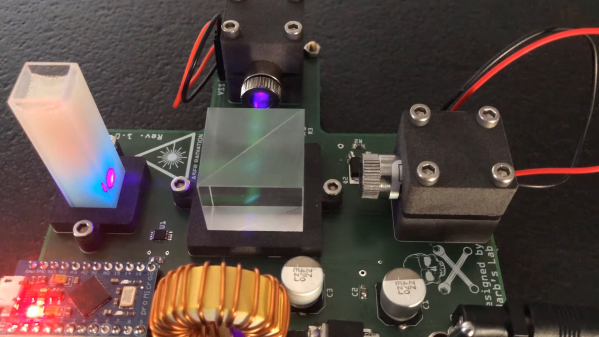
The electronics for this are pretty simple, with two laser modules and their drivers, a power supply, and an Arduino to run everything. The optics are straightforward as well — a beam splitter that directs the beams from each laser onto the target, which is a glass cuvette filled with a clear epoxy resin mixed with a photochromic chemical. [Markus] chose spiropyran as the pigment, which when bathed in UV light undergoes an intramolecular carbon-oxygen bond breakage that turns it into the dark blue pigment merocyanine. Hitting the spot with a red laser or heating the cuvette causes the C-O bond to reform, fading the blue spot.

The video below shows the intensely blue dot spot developing under UV light and rapidly fading thanks to just the ambient temperature. To make the effect last longer, [Markus] cools the target with a spritz from a CO2 cartridge. We imagine other photochromic chemicals could also be employed here, as could some kind of photometric sensor to read the current state of the flip-flop. Even as it is, though, this is an interesting way to put chemistry and optics to work.

Continue reading “This Unique Flip-Flop Uses Chemistry And Lasers”

Neon Lamps — Not Just For Pilot Lights

It’s easy to see why LEDs largely won out over neon bulbs for pilot light applications. But for all the practical utility of LEDs, they’re found largely lacking in at least one regard over their older indicator cousins: charm. Where LEDs are cold and flat, the gentle orange glow of a neon lamp brings a lot to the aesthetics party, especially in retro builds.

But looks aren’t the only thing these tiny glow lamps have going for them, and [David Lovett] shows off some of the surprising alternate uses for neon lamps in his new video. He starts with an exploration of the venerable NE-2 bulb, which has been around forever, detailing some of its interesting electrical properties, like the difference between the voltage needed to start the neon discharge and the voltage needed to maintain it. He also shows off some cool neon lamp tricks, like using them for all sorts of multi-vibrator circuits without anything but a few resistors and capacitors added in. The real fun begins when he breaks out the MTX90 tube, which is essentially a cold cathode thyratron. The addition of a simple control grid makes for some interesting circuits, like single-tube multi-vibrators.

The upshot of all these experiments is pretty clear to anyone who’s been following [David]’s channel, which is chock full of non-conventional uses for vacuum tubes. His efforts to build a “hollow state” computer would be greatly aided by neon lamp circuits such as these — not to mention how cool they’d make everything look.

Continue reading “Neon Lamps — Not Just For Pilot Lights”

Should’ve Used A 555 — Or 276 Of Them

When asked to whip up a simple egg timer, most of us could probably come up with a quick design based on the ubiquitous 555 timer. Add a couple of passives around the little eight-pin DIP, put an LED on it to show when time runs out, and maybe even add a pot for variable timing intervals if we’re feeling fancy. Heck, many of us could do it from memory.

So why exactly did [Jesse Farrell] manage to do essentially the same thing using a whopping 276 555s? Easy — because why not? Originally started as an entry in the latest iteration of our 555 Contest, [Jesse]’s goal was simple — build a functional timer with a digital display using nothing but 555s and the necessary passives. He ended up needing a few transistors and diodes to pull it off, but that’s a minor concession when you consider how many chips he replaced with 555s, including counters, decoders, multiplexers, and display drivers. All these chips were built up from basic logic gates, a latch, and a flip-flop, all made from one or more 555s, or variants like the 556 or 558.

As one can imagine, 276 chips take a lot of real estate, and it took eleven PCBs to complete the timer. A main board acts as the timer’s control panel as well as serving as a motherboard for ten other cards, each devoted to a different block of functions. It’s all neat and tidy, and very well-executed, which is in keeping with the excellent documentation [Jesse] produced. The whole thing is wonderfully, needlessly complex, and we couldn’t be more tickled to feature it.

Continue reading “Should’ve Used A 555 — Or 276 Of Them”

Should Have Used A Vacuum Tube 555

“You should have used a 555” has become a bit of a meme around these parts lately, and for good reason. There seems to be little that these ubiquitous chips can’t be used for, and in a world where code often substitutes for hardware, it’s easy to point to instances where one could have just used a simple timer chip instead.

Definitely not in the meme category, though, is this overkill vacuum tube 555 timer. It comes to us via [David Lovett], aka [Usagi Electric], who has lately caught the “hollow state” electronics bug and has been experimenting with all sorts of vacuum tube recreations of circuits we’re far more used to seeing rendered in silicon than glass. The urge to replicate the venerable 555 in nothing but vacuum tubes is understandable, as it uses little more than a pair of comparators and a flip-flop, circuits [David] has already built vacuum tube versions of. The only part left was the discharge transistor; a pentode was enlisted to stand in for that vital function, making the circuit complete.

To physically implement the design, [David] built a large PCB to hold the 18 vacuum tubes and the handful of resistors and capacitors needed. Mounted on eight outsized leads made from sheet steel, the circuit pays homage to the original 8-pin DIP form of the 555. The video below shows the design and build process as well as testing of all the common modes of operation for the timer chip.

You can check out more of our coverage of [David]’s vacuum tube adventures, which started with his reverse-engineering of an old IBM logic module. And while he did a great job explaining the inner workings of the 555, you might want to take a deeper dive into how the venerable chip came to be.

Continue reading “Should Have Used A Vacuum Tube 555”

Circuit Sculpture Vibration Sensor

Here’s your useful and beautiful circuit for the day — [New Pew]’s vibration sensor takes manual control of the flip-flop inside a 555 timer and lights an LED in response. Use it to detect those vibrations you expect, like laundry machines, or those you only suspect, like the kind that might be coming from your engine. This gadget isn’t super-precise, but it will probably get the job done.

The vibration-detecting bit is a tiny ball bearing soldered to the spring from an old pen, which is tied between the trigger and ground pins of the 555. When the chip is powered with a 9 V battery, nearby vibrations will induce wiggle in the spring, causing the ball bearing to contact the brass rod and completing the circuit. When this happens, the internal flip flop’s output goes high, which turns on the LED. Then the flip flop must be reset with a momentary button. Check out the build video after the break.

Want to pick up Earthly vibrations? You can detect earthquakes with a homemade variable capacitor, a 555, and a Raspberry Pi.

Continue reading “Circuit Sculpture Vibration Sensor”

Vacuum Tube Logic Hack Chat

Join us on Wednesday, December 9th at noon Pacific for the Vacuum Tube Logic Hack Chat with David Lovett!

For most of us, circuits based on vacuum tubes are remnants of a technological history that is rapidly fading from our collective memory. To be sure, there are still applications for thermionic emission, especially in power electronics and specialized switching applications. But by and large, progress has left vacuum tubes in a cloud of silicon dust, leaving mainly audiophiles and antique radio enthusiasts to figure out the hows and whys of plates and grids and filaments.

But vacuum tubes aren’t just for the analog world. Some folks like making tubes do tricks they haven’t had to do in a long, long time, at least since the birth of the computer age. Vacuum tube digital electronics seems like a contradiction in terms, but David Lovett, aka Usagi Electric on YouTube, has fallen for it in a big way. His channel is dedicated to working through the analog building blocks of digital logic circuits using tubes almost exclusively. He has come up with unique circuits that don’t require the high bias voltages typically needed, making the circuits easy to work with using equipment likely to be found in any solid-state experimenter’s lab.

David will drop by the Hack Chat to share his enthusiasm for vacuum tube logic and his tips for exploring the sometimes strange world of flying electrons. Join us as we discuss how to set up your own vacuum tube experiments, learn what thermionic emission can teach us about solid-state electronics, and maybe even get a glimpse of what lies ahead in his lab.

join-hack-chatOur Hack Chats are live community events in the Hackaday.io Hack Chat group messaging. This week we’ll be sitting down on Wednesday, December 9 at 12:00 PM Pacific time. If time zones have you tied up, we have a handy time zone converter.

Click that speech bubble to the right, and you’ll be taken directly to the Hack Chat group on Hackaday.io. You don’t have to wait until Wednesday; join whenever you want and you can see what the community is talking about.

Continue reading “Vacuum Tube Logic Hack Chat”

Restoring An Unusual Piece Of Computing History

Trawling classified ads or sites like Craigslist for interesting hardware is a pastime enjoyed by many a hacker. At a minimum, you can find good deals on used tools and equipment. But if you’re very lucky, you might just stumble upon something really special.

Which is exactly how [John] came into possession of the TRANSBINIAC. Included in a collection of gear that may have once belonged to a silent key, the device is a custom-built solid-state computer that appears to have been assembled in the early 1960s. Featuring a large see-through window not unlike what you might find on a modern gaming computer and a kickstand that tilts it back at a roughly 45° angle, it was obviously built to be shown off. Perhaps it was a teaching aid or even a science fair entry.

After some digging, it looks like the design of the TRANSBINIAC was based on plans published in the January 1960 issue of Electronics Illustrated. Though there are some significant differences. This computer uses eight bistable flip-flip modules instead of the original six, deletes the multiplication circuit, and employs somewhat simplified wiring. Whoever built this machine clearly knew what they were doing, which for the time, is really saying something. This truly unique machine may well have been one of the first privately owned digital computers in the world.

Which is why we’re glad to see [John] trying to restore the device to its former glory. Naturally it’s a little tricky since the computer came with no documentation and its design doesn’t exactly match anything out there. But with the help of other Hackaday.io users, he’s hoping to get everything figured out. It sounds like the first step is to try and diagnose the 2N554 germanium transistor flip-flop modules, as they appear to be behaving erratically. If you have experience with this sort of hardware, feel free to chime in.

We’re supremely proud of the fact that so many of these early computer examples (and the people that are fascinated by them) have recently found their way to Hackaday.io. They’re literally the building blocks on which so much of our modern technology is based on, and the knowledge of how they were designed and operated deserves to live on for future generations to learn from. If it wasn’t for 1960s machines like the TRANSBINIAC or the so-called “Paperclip Computer”, Hackaday might not even exist. It seems like the least we can do is return the favor and make sure they aren’t forgotten.

[Thanks to Yann for the tip.]