Bike-Mounted Synthetic-Aperture Radar Makes Detailed Images

Synthetic-aperture radar, in which a moving radar is used to simulate a very large antenna and obtain high-resolution images, is typically not the stuff of hobbyists. Nobody told that to [Henrik Forstén], though, and so we’ve got this bicycle-mounted synthetic-aperture radar project to marvel over as a result.

Neither the electronics nor the math involved in making SAR work is trivial, so [Henrik]’s comprehensive write-up is invaluable to understanding what’s going on. First step: build a 6-GHz frequency modulated-continuous wave (FMCW) radar, a project that [Henrik] undertook some time back that really knocked our socks off. His FMCW set is good enough to resolve human-scale objects at about 100 meters.

Moving the radar and capturing data along a path are the next steps and are pretty simple, but figuring out what to do with the data is anything but. [Henrik] goes into great detail about the SAR algorithm he used, called Omega-K, a routine that makes use of the Fast Fourier Transform which he implemented for a GPU using Tensor Flow. We usually see that for neural net applications, but the code turned out remarkably detailed 2D scans of a parking lot he rode through with the bike-mounted radar. [Henrik] added an auto-focus routine as well, and you can clearly see each parked car, light pole, and distant building within range of the radar.

We find it pretty amazing what [Henrik] was able to accomplish with relatively low-budget equipment. Synthetic-aperture radar has a lot of applications, and we’d love to see this refined and developed further.

[via r/electronics]

Dirty Video Mixing With The Raspberry Pi Zero

Don’t get too excited now, we aren’t talking about that kind of dirty video. There’s plenty of other places on the Internet you can go to find that sort of thing. No, this video mixer is “dirty” because it combines two composite video streams into one garbled up mess that’s best viewed on an old CRT TV. Why, you may ask? Because rock and roll, that’s why.

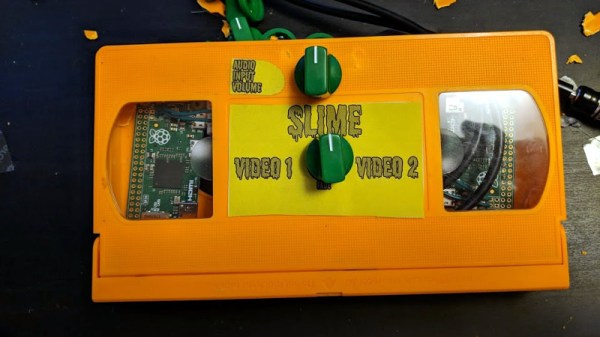
Created by [Luke Blackford] as a visual for his band’s performances, the “Dirty Pi” is an exceptionally simple way to create some wild imagery with two Raspberry Pi Zeros. It might not be the most practical of devices, but if you want so throw some creepy looking video up on screens all over the house (say for an upcoming Halloween party), this is a fantastic way to do it on the cheap.

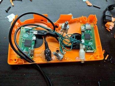
The idea is simple: connect the oft-forgotten composite video outputs of two Pi Zeros to a potentiometer, which then leads to the display. Play different videos on the Pis with the media player of your choice, and twiddle the potentiometer to create ghosting and interference. If you want to get that true 1980’s retro feel, put the whole thing into an old VHS cassette like [Luke] did, and you’re ready to rock.

Those who’ve been around the block a few times might recognize this trick as a variation of the [Karl Klomp] Dirty Video Mixer, and [Luke] tells us he likes this project because he was able to pull it off without writing any code or even doing any complex wiring, though he does imagine a future version where he adds some remote control functionality.

If you like your video mixers with more smarts and less dirt, we’ve covered a very slick build using the LM1881 in the past.

Continue reading “Dirty Video Mixing With The Raspberry Pi Zero”

A Radar Module Teardown And Measuring Fan Speed The Hard Way

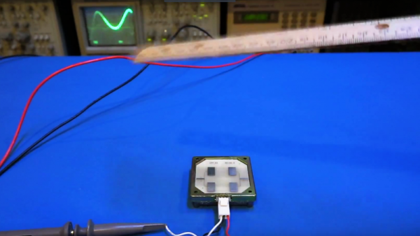
If you have even the slightest interest in microwave electronics and radar, you’re in for a treat. The Signal Path is back with another video, and this one covers the internals of a simple 24-GHz radar module along with some experiments that we found fascinating.

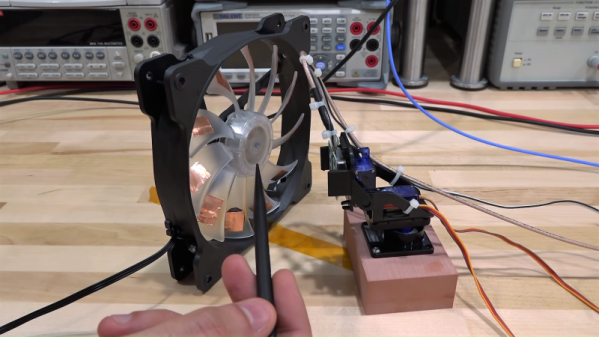
The radar module that [Shahriar] works with in the video below is a CDM324 that can be picked up for a couple of bucks from the usual sources. As such it contains a lot of lessons in value engineering and designing to a price point, and the teardown reveals that it contains but a single active device. [Shahriar] walks us through the layout of the circuit, pointing out such fascinating bits as capacitors with no dielectric, butterfly stubs acting as bias tees, and a rat-race coupler that’s used as a mixer. The flip side of the PCB has two arrays of beam-forming patch antennas, one for transmit and one for receive. After a few simple tests to show that the center frequency of the module is highly variable, he does a neat test using gimbals made of servos to sweep the signal across azimuth and elevation while pointing at a receiving horn antenna. This shows the asymmetrical nature of the beam-forming array. He finishes up by measuring the speed of a computer fan using the module, which has some interesting possibilities in data security as well as a few practical applications.

Even though [Shahriar]’s video tend to the longish side, he makes every second count by packing in a lot of material. He also makes complex topics very approachable, like what’s inside a million-dollar oscilloscope or diagnosing a wonky 14-GHz spectrum analyzer.

Continue reading “A Radar Module Teardown And Measuring Fan Speed The Hard Way”

The Hot And Cold Of Balanced Audio

A few summers of my misspent youth found me working at an outdoor concert venue on the local crew. The local crew helps the show’s technicians — don’t call them roadies; they hate that — put up the show. You unpack the trucks, put up the lights, fly the sound system, help run the show, and put it all back in the trucks at the end. It was grueling work, but a lot of fun, and I got to meet people with names like “Mister Dog Vomit.”

One of the things I most remember about the load-in process was running the snakes. The snakes are fat bundles of cables, one for audio and one for lighting, that run from the stage to the consoles out in the house. The bigger the snakes, the bigger the show. It always impressed me that the audio snake, something like 50 yards long, was able to carry all those low-level signals without picking up interference from the AC thrumming through the lighting snake running right alongside it, while my stereo at home would pick up hum from the three-foot long RCA cable between the turntable and the preamp.

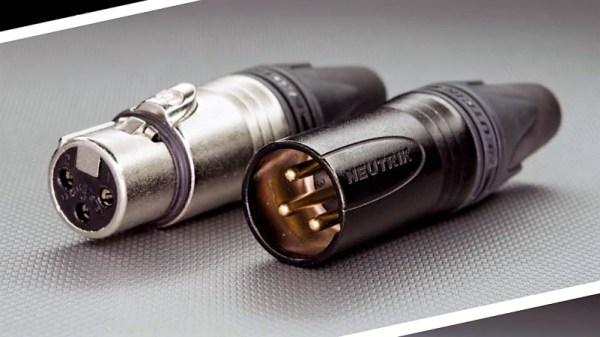
I asked one of the audio techs about that during one show, and he held up the end of the snake where all the cables break out into separate connectors. The chunky silver plugs clinked together as he gave his two-word answer before going back to patching in the console: “Balanced audio.”

Continue reading “The Hot And Cold Of Balanced Audio”

Understanding A MOSFET Mixer

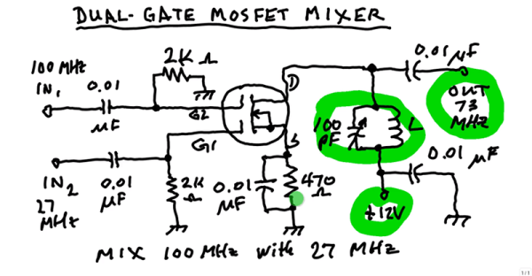
A mixer takes two signals and mixes them together. The resulting output is usually both frequencies, plus their sum and their difference. For example, if you feed a 5 MHz signal and a 20 MHz signal, you’d get outputs at 5 MHz, 15 MHz, 20 MHz, and 25 MHz. In a balanced mixer, the original frequencies cancel out, although not all mixers do that or, at least, don’t do it perfectly. [W1GV] has a video that explains the design of a mixer with a dual gate MOSFET, that you can see below.

The dual gate MOSFET is nearly ideal for this application with two separate gates that have effectively infinite input impedance. [Stan] takes you through the basic circuit and explains the operation in whiteboard fashion.

Continue reading “Understanding A MOSFET Mixer”

A Passive Mixer’s Adventure Through Product Development

The year was 2014, and KORG’s volca line of pint-sized synthesizers were the latest craze in the music world. Cheap synths and drum machines were suddenly a reality, all in a backpack-friendly form factor. Now practically anyone could become an electronic music sensation!

I attended a jam with friends from my record label, and as was the style at the time, we all showed up with our latest and greatest gear. There was the microKORG, a MiniNova, and a couple of guitars, but all attention was on the volcas, which were just so much fun to pick up and play with.

There was just one problem. Like any game-changing low-cost hardware, sacrifices had been made. The volcas used 3.5mm jacks for audio and sync pulses, and the initial lineup came with a bassline, lead, and drum synth. Syncing was easy, by daisy chaining cables between the boxes, but if you wanted to record or mix, you’d generally need to stack adapters to get your signals in a more typical 6.5mm TS format used by other music hardware.

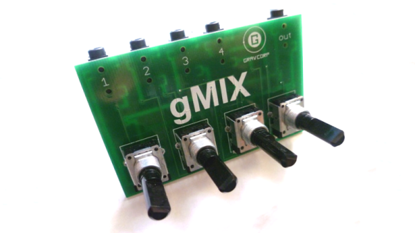
After mucking around, I did some research on what other people were doing. Most were suffering just like we were, trying to patch these little machines into full-sized mixing desks. It seemed like overkill — when you just want to muck around, it’s a bit much to drag out a 24 channel powered mixer. I wanted a way to hook up 3 of these machines to a single set of headphones and just groove out.

To solve this problem, we needed a mixer to match the philosophy of the volcas; simple, accessible, and compact. It didn’t need to be gold-plated or capable of amazing sonic feats, it just had to take a few 3.5mm audio sources, and mix them down for a pair of headphones.

I’d heard of people using headphone splitters with mixed results, and it got me thinking about passive mixing. Suddenly it all seemed so clear — I could probably get away with a bunch of potentiometers and some passives and call it a day! With a friend desperate to get their hands on a solution, I decided to mock up a prototype and took it round to the studio to try out.

Continue reading “A Passive Mixer’s Adventure Through Product Development”

Doppler Module Teardown Reveals The Weird World Of Microwave Electronics

Oscillators with components that aren’t electrically connected to anything? PCB traces that function as passive components based solely on their shape? Slots and holes in the board with specific functions? Welcome to the weird and wonderful world of microwave electronics, brought to you through this teardown and analysis of a Doppler microwave transceiver module.

We’ve always been fascinated by the way conventional electronic rules break down as frequency increases. The Doppler module that [Kerry Wong] chose to pop open, a Microsemi X-band transceiver that goes for about $10 on eBay right now, has vanishingly few components inside. One transistor for the local oscillator, one for the mixer, and about three other passives are the whole BOM. That the LO is tuned by a barium titanate slug that acts as a dielectric resonator is just fascinating, as is the fact that PB traces can form a complete filter network just by virtue of their size and shape. Antennas that are coupled to the transceiver through an air gap via slots in the board are a neat trick too.

[Kerry] analyzes all this in the video below and shows how the module can be used as a sensor. If you need a little more detail on putting these modules to work, we’ve got some basic circuits you can check out.

Continue reading “Doppler Module Teardown Reveals The Weird World Of Microwave Electronics”