The Galaxy Fold, Or Why Flexible OLED May Not Yet Be Ready For Prime Time

Samsung’s fancy new high-end smartphone with a flexible, foldable OLED display has been failing in worrying numbers for the first reviewers who got their hands on one. Now iFixit has looked into the issue using their considerable amount of smartphone tear-down experience to give their two cents. They base many of their opinions on the photos and findings by the Verge review, who were one of the (un)lucky ones to have their unit die on them.

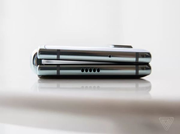
The Galaxy Fold was supposed to be this regular smartphone sized phone which one can open up fully to reveal a tablet-sized display inside. The use of a flexible OLED display was supposed to create a seamless display without the annoying center line that having two individual displays would produce. Unfortunately it’s this folding feature which produces issues.

As iFixit notes, OLEDs are rather fragile, with their own tear-downs of regular OLED-equipped devices already often resulting in the damaging of the display edges, which spells doom for the internals of them as oxygen and other contaminants can freely enter. This means that maintaining this barrier is essential to keep the display functioning.

This is probably the reason why Samsung chose to install a screen protector on the display, which unfortunately was mistaken for a protective foil as found on many devices. The subsequent removal of this protector by some reviewers and the mechanical stress this caused destroyed some screens. Others had debris trapped in the fold between both halves of the display, which caused visible bumps in the display when opened.

The relatively massive spacing between the hinge and the display seems almost purposefully engineered to allow for the ingress of debris. This combines with the lack of any guiding crease in the center of the display and the semi-random way in which humans open and close the Fold compared to the perfectly repeating motion of the folding robots Samsung used to test the display. It seems that Samsung and others still have some work to do before they can call folding OLED displays ready for production.

Finally, have a look at this video of Lewis from UnboxTherapy pulling a folding robot with opening and closing a Fold one-thousand times:


This GPS Speedometer Hangs Off Your Handlebars

If you can ride a bike with no handlebars, no handlebars, no handlebars, you can do just about anything. You can take apart a remote control, and you can almost put it back together. You can listen in on a two meter repeater and you can build a GPS module speedometer. That’s what [Jeremy Cook] did with just a few parts, a little 3D design, and some handy zip ties to hold it onto the handlebars, the handlebars.

The electronics for this build are relatively simple, based on an Arduino Pro Mini because that’s just about the smallest readily available development board you’ll be able to find. To this is a LiPo, a LiPo charging circuit, a GPS module, and a single RGB LED. The code gets some data from the GPS module and figures out a speed. This is then translated into a color — red, yellow, or green depending on whether you’re stationary, below 5 km/h, or above 5 km/h.

All these electronics are stuffed into a 3D-printed enclosure. The majority of the enclosure is printed in black, with a translucent top that serves as a great diffuser for the LED. Just two zip ties hold this GPS speedometer onto the handlebars, and from the video below, everything looks great. The GPS module does take some time to get data at first, but that’s a common problem with GPS units that have been powered off for a few days. If only someone made a GPS module that could keep time with no metronome, with no metronome.

Continue reading “This GPS Speedometer Hangs Off Your Handlebars”

House Training A Military TA-1024A Field Telephone

After spotting some interesting military phones at a museum, [CuriousMarc] wondered what it would take to retrofit these heavy duty pieces of telecom equipment for civilian use. He knew most of the internals would be a lost cause, but reasoned that if he could reverse engineer key elements such as the handset and keypad, he might be able to connect them to the electronics of a standard telephone. Luckily for us, he was kind enough to document the process.

There were a number of interesting problems that needed to be solved, but the first and perhaps largest of them was the unusual wiring of the keypad. It wasn’t connected in the way modern hackers like us might expect, and [CuriousMarc] had to end up doing some pretty significant rewiring. By cutting the existing traces on the PCB with a Dremel and drilling new holes to run his wires around the back, he was able to convert it over to a wiring scheme that contemporary touch tone phones could use.

An adapter needed to be fabricated to mount a basic electret microphone in place of the original dynamic one, but the original speaker was usable. He wanted to adapt the magnetic sensor that detected when the handset was off the hook, but in the end it was much easier to just drill a small hole and use a standard push button.

The main board of the phone is a perfect example of the gorgeous spare-no-expense construction you’d expect from a military communications device, but unfortunately it had to go in the bin. In its place is the guts of a lowly RCA phone that was purchased for the princely sum of $9.99. [CuriousMarc] won’t be able to contact NORAD anymore, but at least he’ll be able to order a pizza. The red buttons on the keypad, originally used to set the priority level of the call on the military’s AUTOVON telephone network, have now been wired to more mundane features of the phone such as redial.

While this is fine for a one-off project, we’d love to see a drop-in POTS or VoIP conversion for these phones that didn’t involve so much modification and rewiring. Now that we have some documentation for things like the keypad and hook sensor, it shouldn’t be hard to take their idiosyncrasies into account with a custom PCB. Dragging vintage gear into the modern era is always a favorite pastime for hackers, so maybe somebody out there will be inspired to take on the challenge.

Continue reading “House Training A Military TA-1024A Field Telephone”

A DIY EMC Probe From Semi-Rigid Coax And An SDR

Do you have an EMC probe in your toolkit? Probably not, unless you’re in the business of electromagnetic compatibility testing or getting a product ready for the regulatory compliance process. Usually such probes are used in anechoic chambers and connected to sophisticated gear like spectrum analyzers – expensive stuff. But there are ways to probe the electromagnetic mysteries of your projects on the cheap, as this DIY EMC testing setup proves.

As with many projects, [dimtass]’ build was inspired by a video over on EEVblog, where [Dave] made a simple EMC probe from a length of semi-rigid coax cable. At $10, it’s a cheap solution, but lacking a spectrum analyzer like the one that [Dave] plugged his cheap probe into, [dimtass] went a different way. With the homemade probe plugged into an RTL-SDR dongle and SDR# running on a PC, [dimtass] was able to get a decent approximation of a spectrum analyzer, at least when tested against a 10-MHz oven-controlled crystal oscillator. It’s not the same thing as a dedicated spectrum analyzer – limited bandwidth, higher noise, and not calibrated – but it works well enough, and as [dimtass] points out, infinitely hackable through the SDR# API. The probe even works decently when plugged right into a DSO with the FFT function running.

Again, neither of these setups is a substitute for proper EMC testing, but it’ll probably do for the home gamer. If you want to check out the lengths the pros go through to make sure their products don’t spew signals, check out [Jenny]’s overview of the EMC testing process.

[via RTL-SDR.com]

Prusa Launches Their Own 3D Model Repository

If you own a 3D printer, you’ve heard of Thingiverse. The MakerBot-operated site has been the de facto model repository for 3D printable models since the dawn of desktop 3D printing, but over the years it’s fallen into a state of disrepair. Dated and plagued with performance issues, many in the community have been wondering how long MakerBot is still going to pay to keep the lights on. Alternatives have popped up occasionally, but so far none of them have been able to amass a large enough userbase to offer any sort of real competition.

Sorting models by print time and material required.

But that might soon change. [Josef Průša] has announced a revamped community for owners of his 3D printers which includes a brand-new model repository. While clearly geared towards owners of Prusa FDM printers (support for the new SLA printer is coming at a later date), the repository is not exclusive to them. The immense popularity of Prusa’s products, plus the fact that the repository launched with a selection of models created by well known designers, might be enough to finally give Thingiverse a run for its money. Even if it just convinces MakerBot to make some improvements to their own service, it would be a win for the community.

The pessimists out there will say a Prusa-run model database is ultimately not far off from one where MakerBot is pulling the strings; and indeed, a model repository that wasn’t tied to a particular 3D printer manufacturer would be ideal. But given the passion for open development demonstrated by [Josef] and his eponymous company, we’re willing to bet that the site is never going to keep owners of other printers from joining in on the fun.

That being said, knowing that the users of your repository have the same printer (or a variant, at least) as those providing the designs does have its benefits. It allows for some neat tricks like being able to sort designs by their estimated print time, and even offers the ability to upload and download pre-sliced GCode files in place of traditional STLs. In fact, [Josef] boasts that this is the world’s only repository for ready-to-print GCode that you can just drop onto an SD card and print.

Regular Hackaday readers will know that we’ve been rather critical of the decisions made by MakerBot over the last few years, but to be fair we aren’t exactly alone in that respect. The community desperately needs a repository for printable models that’s in somebody else’s hands, and frankly we’re thrilled with the idea it could be [Josef Průša] leading the charge. His printers might not be perfect, and they certainly aren’t cheap, but they definitely don’t fail to impress. Here’s hoping this latest venture will be the same.

Continue reading “Prusa Launches Their Own 3D Model Repository”

Give Your Solar Garden Lights A Color Changing LED Upgrade

White LEDs were the technological breakthrough that changed the world of lighting, now they are everywhere. There’s no better sign of their cost-effective ubiquity than the dollar store solar garden light: a complete unit integrating a white LED with its solar cell and battery storage. Not content with boring white lights on the ground, [Emily] decided to switch up their colors with a mix of single-color LEDs and dynamic color-changing LEDs, then hung them up high as colorful solar ornaments.

The heart of these solar devices is a YX8018 chip (or one of its competitors.) While the sun is shining, solar power is directed to charge up the battery. Once the solar cell stops producing power, presumably because the sun has gone down, the chip starts acting as a boost converter (“Joule thief”) pushing a single cell battery voltage up high enough to drive its white LED. Changing that LED over to a single color LED is pretty straightforward, but a color changing LED adds a bit of challenge. The boost converter deliver power in pulses that are too fast for human eyes to pick up but the time between power pulses is long enough to cause a color-changing circuit to reset itself and never get beyond its boot-up color.

The hack to keep a color-changing LED’s cycle going is to add a capacitor to retain some charge between pulses, and a diode to prevent that charge from draining back into the rest of the circuit. A ping-pong ball serves as light diffuser, and the whole thing is hung up using a 3D-printed sheath which adds its own splash of color.

Solar garden lights are great basis for a cheap and easy introduction to electronics hacking. We’ve seen them turn into LED throwies, into a usable flashlight, or even to power an ATTiny microcontroller.

Continue reading “Give Your Solar Garden Lights A Color Changing LED Upgrade”

GPS Self-Adjusting Clock With An E-Ink Display

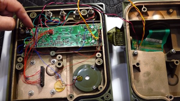
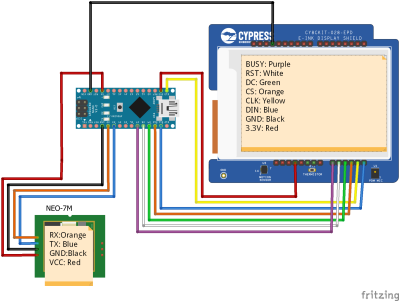
If you mention a clock that receives its time via radio, most people will think of one taking a long wave signal from a station such as WWVB, MSF, or DCF77. A more recent trend however has been for clocks that set themselves from orbiting navigation satellites, and an example comes to us from [KK99].  It’s a relatively simple hardware build in that it is simply an Arduino Nano, GPS module, and e-ink display module wired together, but it provides an interesting exercise in running through the code required for a GPS clock.

It does however give us a chance to remember the story from last year surrounding WWVB, as a budget proposal last year mooted the prospect of the closure of the Fort-Collins-based time signal transmitter. Were that to happen an estimated 50 million American clocks would lose their reference, and while their owners could always update them manually, there will always be time-based systems to which that won’t be applied for whatever reason.  Europeans meanwhile are safe in their time transmissions for now , but in case they think they have their mains grid to fall back on it’s worth remembering the time they lost six seconds.

GPS satellite image: USAF [Public domain].