The UMPC powered up, case-less showing the black PCB, with the display standing upwards and showing a blue colour scheme desktop with a CLI terminal open. To the right of it is one of the UMPCs that served as an inspiration for this project.

Bringing The UMPCs Back With A Pi Zero

Miss PDAs and UMPCs? You wouldn’t be the only one, and it’s a joy to see someone take the future into their own hands. [Icepat]’s dream is reviving UMPCs as a concept, and he’s bringing forth a pretty convincing hardware-backed argument in form of the Pocket Z project. For the hardware design, he’s hired two engineers, [Adam Nowak] and [Marcin Turek], and the 7-inch Pocket Z7 version is coming up quite nicely!

The Hackaday.io project shows an impressive gallery of inspiration devices front and center, and with these in mind, the first version of the 7-inch UMPC sets the bar high. With a 1024×600 parallel RGB (DPI) touchscreen display, an ATMega32U4-controlled keyboard, battery-ready power circuitry, and a socketed Pi Zero for brains, this device shows a promising future for the project, and we can’t wait to see how it progresses.

While it’s not a finished project just yet, this effort brings enough inspiration all around, from past device highlights to technical choices, and it’s worth visiting it just for the sentiment alone. Looking at our own posts, UMPCs are indeed resurfacing, after a decade-long hiatus – here’s a Sidekick-like UMPC with a Raspberry Pi, that even got an impressive upgrade a year later! As for PDAs, the Sharp memory LCD and Blackberry keyboard combination has birthed a good few projects recently, and, who can forget about the last decade’s introductions to the scene.

Pixel Art And The Myth Of The CRT Effect

The ‘CRT Effect’ myth says that the reason why pixel art of old games looked so much better is due to the smoothing and blending effects of cathode-ray tube (CRT) displays, which were everywhere until the early 2000s. In fits of mistaken nostalgia this has led both to modern-day extreme cubism pixel art and video game ‘CRT’ filters that respectively fail to approach what pixel art was about, or why old games looked the way they did back with our NES and SNES game consoles. This is a point which [Carl Svensson] vehemently argues from a position of experience, and one which is likely shared by quite a few of our readers.

Although there is some possible color bleed and other artefacts with CRTs due to the shadow mask (or Sony’s Trinitron aperture grille), there was no extreme separation between pixels or massive bleed-over into nearby pixels to create some built-in anti-aliasing as is often claimed unless you were using a very old/cheap or dying CRT TV. Where such effects did happen was mostly in the signal being fed into the CRT, which ranged from the horrid (RF, composite) to the not-so-terrible (S-Video, component) to the sublime (SCART RGB), with RGB video (SCART or VGA) especially busting the CRT effect myth.

Where the pixel art of yester-year shines is in its careful use of dithering and anti-aliasing to work around limited color palettes and other hardware limitations. Although back in the Atari 2600 days this led to the extreme cubism which we’re seeing again in modern ‘retro pixel art’ games, yesterday’s artists worked with the hardware limitations to create stunning works of arts, which looked great on high-end CRTs connected via RGB and decent via composite on the kids’ second-hand 14″ color set with misaligned electron guns.

D+ and D- wires from a USB cable connected to GPIO pins on the Pi Pico, using a female header plugged onto the jumper wires

Need A USB Sniffer? Use Your Pico!

Ever wanted to sniff USB device communications? The usual path was buying an expensive metal box with USB connectors, using logic analyzers, or wiring devboards together and hacking some software to make them forward USB data.

Now, thanks to [ataradov]’s work, you can simply use a Pi Pico – you only need to tap the D+ and D- pins, wire them to RP2040’s GPIOs, and you can sniff communication between your computer and any low-speed (1.5 Mbps) or full-speed (12 Mbps) devices. On the RP2040 side, plug the Pico into your computer, open the virtual serial port created, and witness the USB packets streaming in – for the price of a Pico, you get an elegant USB sniffer, only a little soldering required.

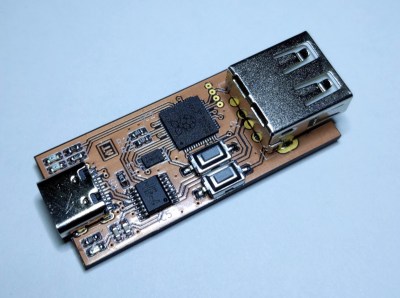
[ataradov] also offers us a complete board design with a RP2040 and a USB hub on it, equipped with USB sockets that completely free us from the soldering requirement; it’s an open-source KiCad design, so you can simply order some  sniffers made from your favourite fab! This project is a great learning tool, it’s as cheap and easy to make as humanly possible, and it has big potential for things like reverse-engineering old and new systems alike. Just couple this hack with another Pico doing USB device or host duty, maybe get up to date with USB reverse-engineering fundamentals, and you could make a Facedancer-like tool with ease.

Need to reach 480 Mbit/s? [ataradov] has a wonderful board for you as well, that we have covered last year – it’s well worth it if a device of yours can only do the highest speed USB2 can offer, and, it offers WireShark support. Want WireShark support and to use a Pico? Here’s a GitHub project by another hacker, [tana]. By now, merely having a Pi Pico gives you so many tools, it’s not even funny.

We thank [Julianna] for sharing this with us!

Steamdeck motherboard standing upright propped onto a USB-C dock it's wired up to, showing just how little you need to make the steamdeck board work.

Steam Deck, Or Single Board Computer?

With a number of repair-friendly companies entering the scene, we have gained motivation to dig deeper into devices they build, repurpose them in ways yet unseen, and uncover their secrets. One such secret was recently discovered by [Ayeitsyaboii] on Reddit – turns out, you can use the Steam Deck mainboard as a standalone CPU board for your device, no other parts required aside from cooling.

All you need is a USB-C dock with charging input and USB/video outputs, and you’re set – it doesn’t even need a battery plugged in. In essence, a Steam Deck motherboard is a small computer module with a Ryzen CPU and a hefty GPU! Add a battery if you want it to work in UPS mode, put an SSD or even an external GPU into the M.2 port, attach WiFi antennas for wireless connectivity – there’s a wide range of projects you can build.

Each such finding brings us closer to the future of purple neon lights, where hackers spend their evenings rearranging off-the-shelf devices into gadgets yet unseen. Of course, there’s companies that explicitly want us to hack their devices in such a manner – it’s a bet that Framework made to gain a strong foothold in the hacker community, for instance. This degree of openness is becoming a welcome trend, and it feels like we’re only starting to explore everything we can build – for now, if your Framework’s or SteamDeck’s screen breaks, you always have the option to build something cool with it.

[Via Dexerto]

Homebrew Relay Computer Features Motorized Clock

Before today, we probably would have said that scratch-built relay computers were the sole domain of only the most wizardly of graybeards. But this impressive build sent in by [Will Dana] shows that not only are there young hardware hackers out there that are still bold enough to leave the transistor behind, but that they can help communicate how core computing concepts can be implemented with a bundle of wires and switches.

Created for his YouTube channel WillsBuilds, every component of this computer was built by [Will] himself. Each of the nine relay-packed protoboards inside the machine took hours to solder, and when that was done, he went out to the garage to start cutting the wood that would become the cabinet they all get mounted in.

Continue reading “Homebrew Relay Computer Features Motorized Clock”

How About Privacy and Hackability?

Many smart electric meters in the US use the 900 MHz band to broadcast their usage out to meter readers as they walk the neighborhood. [Jeff Sandberg] used an RTL-SDR dongle and some software to integrate this data into his own home automation system, which lets him keep track of his home’s power usage.

Half of the comment section was appalled that the meters broadcast this data in the clear, and these readers thought this data should be encrypted even if the reach is limited to the home-owner’s front yard. But that would have stopped [Jeff] from accessing his own data as well, and that would be a shame. So there’s clearly a tradeoff in play here.

We see this tradeoff in a lot of hardware devices as well – we want to be able to run our firmware on them, but we don’t want criminals to do the same. We want the smart device to work with the cloud service, but to also work with our own home automation system if we have one. And we want to be able to listen in to our smart meters, but don’t necessarily want others to do so.

The solution here is as easy as it is implausible that it will get implemented. If the smart meters transmitted encrypted, each with their own individual password, then everyone would win. The meter reader would have a database of passwords linked to meter serial numbers or addresses, and the home owner could just read it off of a sticker, optimally placed on each unit. Privacy and usability would be preserved.

This issue isn’t just limited to electric meters. Indeed, think of all of the data that is being sent out from or about you, and what percentage of it is not encrypted and should be, but also about what data is sent out encrypted that you could use access to. The solution is to put you in control of the encryption, by selecting a password or having access to one that’s set for you. Because after all, if it’s your data, it should be your data: private and usable.

Get Your Glitch On With A PicoEMP And A 3D Printer

We’re not sure what [Aaron Christophel] calls his automated chip glitching setup built from a 3D printer, but we’re going to go ahead and dub it the “Glitch-o-Matic 9000.” Has a nice ring to it.

Of course, this isn’t a commercial product, or even a rig that’s necessarily intended for repeated use. It’s more of a tactical build, which is still pretty cool if you ask us. It started with a proof-of-concept exploration, summarized in the first video below. That’s where [Aaron] assembled and tested the major pieces, which included a PicoEMP, the bit that actually generates the high-voltage pulses intended to scramble a running microcontroller temporarily, along with a ChipWhisperer and an oscilloscope.

The trouble with the POC setup was that glitching the target chip, an LPC2388 microcontroller, involved manually scanning the business end of the PicoEMP over the package. That’s a tedious and error-prone process, which is perfect for automation. In the second video below, [Aaron] has affixed the PicoEMP to his 3D printer, giving him three-axis control of the tip position. That let him build up a heat map of potential spots to glitch, which eventually led to a successful fault injection attack and a clean firmware dump.

It’s worth noting that the whole reason [Aaron] had to resort to such extreme measures in the first place was the resilience of the target chip against power supply-induced glitching attacks. You might not need to build something like the Glitch-o-Matic, but it’s good to keep in mind in case you run up against such a hard target. Continue reading “Get Your Glitch On With A PicoEMP And A 3D Printer”