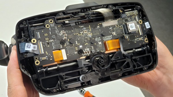
It’s been just over a year since Valve released Index, their flagship VR system, and it’s worth looking back at this GitHub repository as a fine example of how to provide supporting materials to a hacker-friendly hardware design. The image above shows off one of the hacker-friendly design elements: an empty space behind the visor, with a USB port off to the right, that exists for no reason other than to make it easier to mount and plug in whatever one might come up with. There’s more to it than that, however. If one wishes to provide supporting materials for a hardware design, one could certainly do worse than emulate Valve’s example.
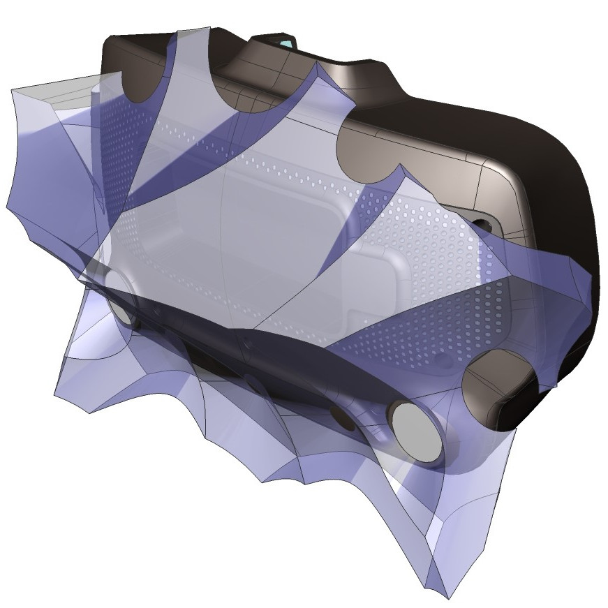
The hardware repository contains not just CAD models of mod-friendly hardware pieces (both in high-resolution STEP models as well as STL files) but also 3D models of the sensor zones, so modders can ensure they avoid occluding any sensors with their creations. Examples are great, and one provided by Valve is the Booster; a hand controller add-on providing extra comfort for people with large hands or long thumbs. The model also doubles as a reference for designing attachments that will not interfere with any of the tracking or touch-sensitive surfaces of the controllers.
Being hacker-friendly doesn’t mean the hardware has no warranty, but it does mean that there is concrete guidance on what does or doesn’t risk voiding it. In the case of the Index hardware, the guidance is simple: “Anything that requires a T5 or smaller is not user serviceable.”
To us, the whole attitude of being hacker-friendly is exemplified by a statement about the headstrap, found about half-way down the page. The words “removing the headstrap is not recommended” are followed immediately by clear directions on how to do exactly that, demonstrating the kind of trust necessary to reduce barriers for add-ons and modifications. That is a great way to help foster experimentation, like this project for 1:1 mapping of physical elements to their VR counterparts, to make awesome spaceship cockpits.