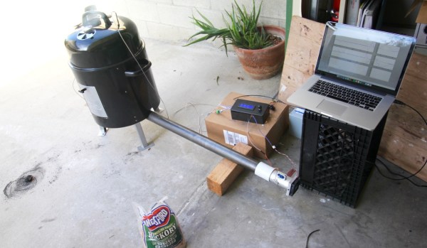
[Jason] learned a lot by successfully automating this meat smoker. This is just the first step in [Jason’s] smoker project. He decided to begin by hacking a cheaper charcoal-fed unit first, before setting his sights on building his own automatic pellet-fed smoker. With a charcoal smoker it’s all about managing the airflow to that hot bed of coals.
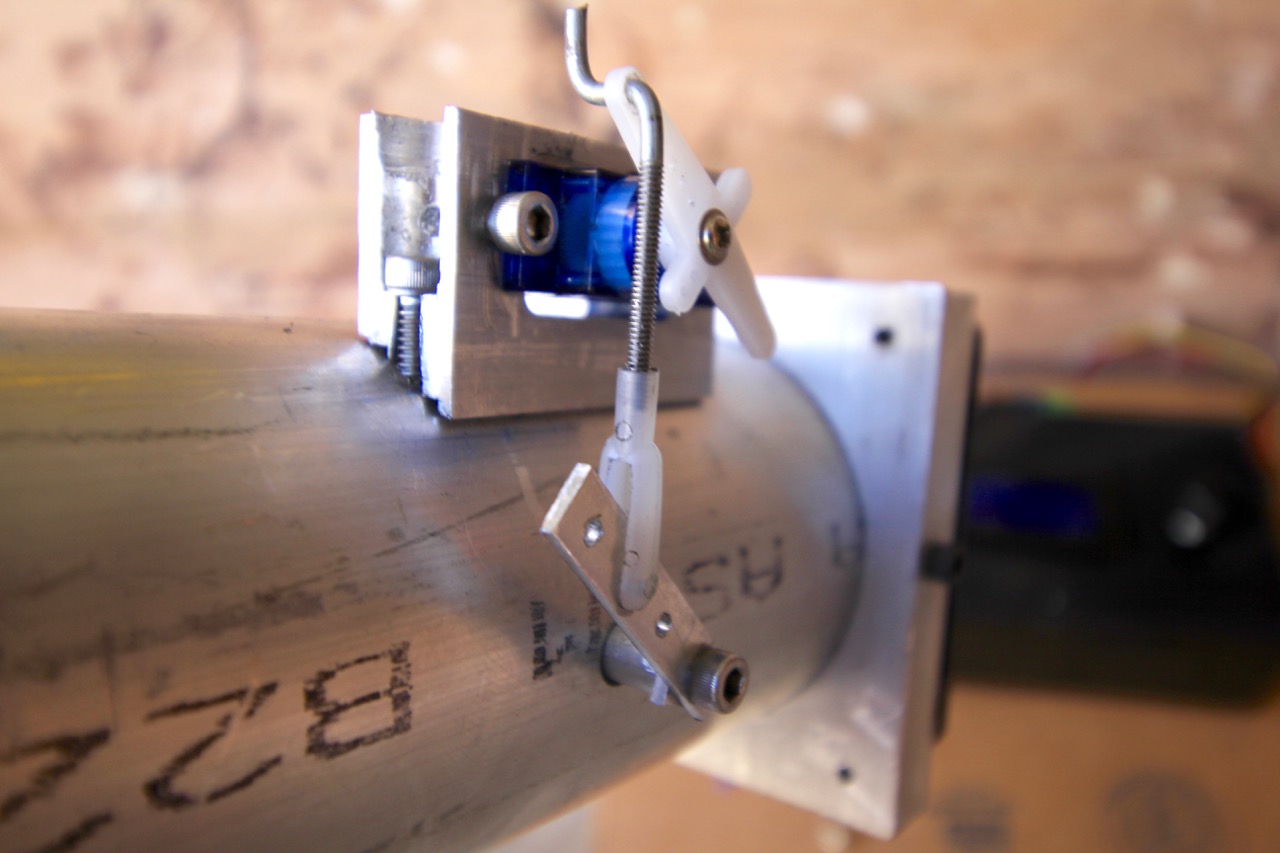
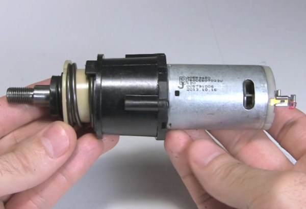
[Jason] started by making sure the bottom was sealed off from stray airflow, then he cut a hole into the charcoal pan and attached a length of steel pipe. The opposite end of the pipe has a fan. Inside the pipe there is a baffle separating the fan from the charcoal pan. The servo motor shown here controls that valve.
The pipe is how air is introduced into the smoker, with the fan and valve to control the flow rate. The more air, the higher the temperature. The hunk of pipe was left uncut and works fine but is much longer than needed; [Jason says] the pipe is perfectly cool to the touch only a foot and a half away from the smoker.
With the actuators in place he needed a feedback loop. A thermocouple installed into the lid of the smoker is monitored by an Arduino running a PID control loop. This predicts the temperature change and adjusts the baffle and fan to avoid overshooting the target temp. The last piece of hardware is a temperature probe inside the meat itself. With the regulation of the smoker’s temperature taken care of and the meat’s internal temperature being monitored, the learning (and cooking) process is well underway.
There are many, many smoker automation projects out there. Some smokers are home-made electric ones using flower pots, and some focus more on modifying off the shelf units. In a way, every PID controlled smoker is the same, yet they end up with different problems to solve during their creation. There is no better way to learn PID than putting it into practice, and this way to you get a tasty treat for your efforts.
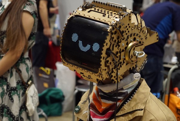
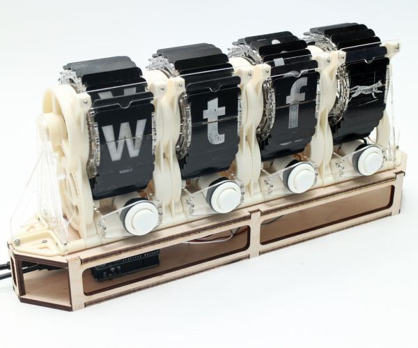
 Part performance art and part social experiment, [mocymo]’s