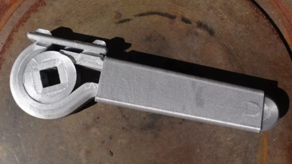
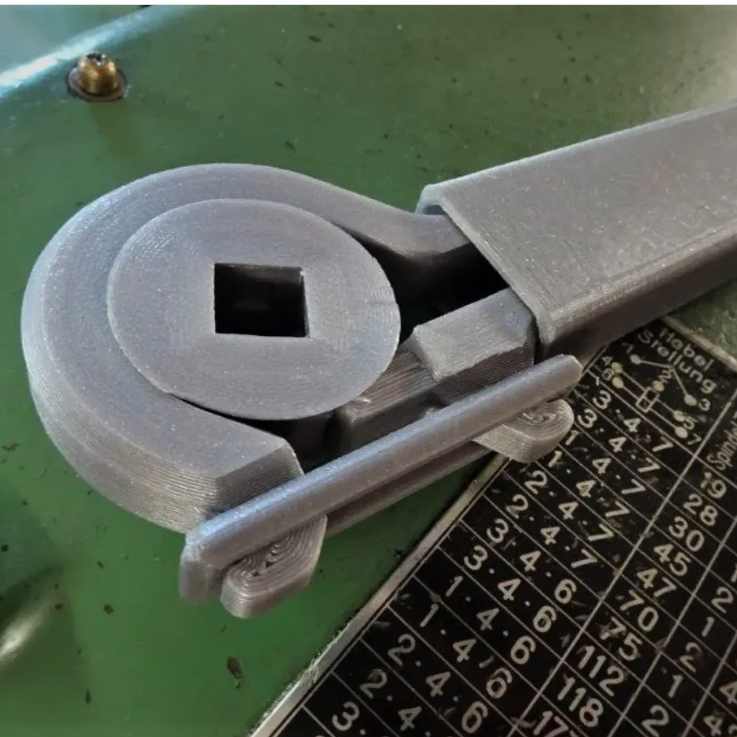
Look closely, and you can see that the parts are almost entirely made up of perimeters (click to enlarge).
This particular wrench is inspired by NASA’s 3D printed ratcheting wrench, and also from an early 1900s design. It sports a 1/2 inch square socket into which modern adapters can be fitted, allowing those steel parts to do their job while the wrench itself delivers the muscle.
[Gladius] found that the strongest results came from slicing parts — especially the handle — so that they come out consisting almost entirely of perimeters, with virtually no traditional infill. Want to know more? There’s a discussion on reddit where [Gladius] goes into added detail about measurements and performance.
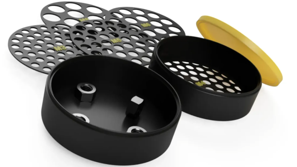
Got a pile of mixed hex nuts? Sort them in no time by printing [jonafriendj]’s nut sorter, which has options for pretty much any nut size you’d be after (it’s labeled metric, but actually includes Imperial sizes as well.)
Something to admire about the design is the handy little raised labels on each of the sieves, and the fact that all the parts print entirely without supports. Designing a part to play to a manufacturing method’s strengths (and avoid its weaknesses) is good DFM, or Design for Manufacturing.
With 3D printing being the boon that it is to workshops and hobbyists everywhere, it certainly pays to strive for good DFM, especially for designs meant to be shared with others. Sometimes good DFM takes a page from other manufacturing methods like injection molding, and we end up with things like using crush ribs on printed parts.
Want to see a demonstration of [jonafriendj]’s nut sorting design? Check out the short video embedded below the page break. If that leaves you wanting, take a look at a motorized, automated DIY solution.
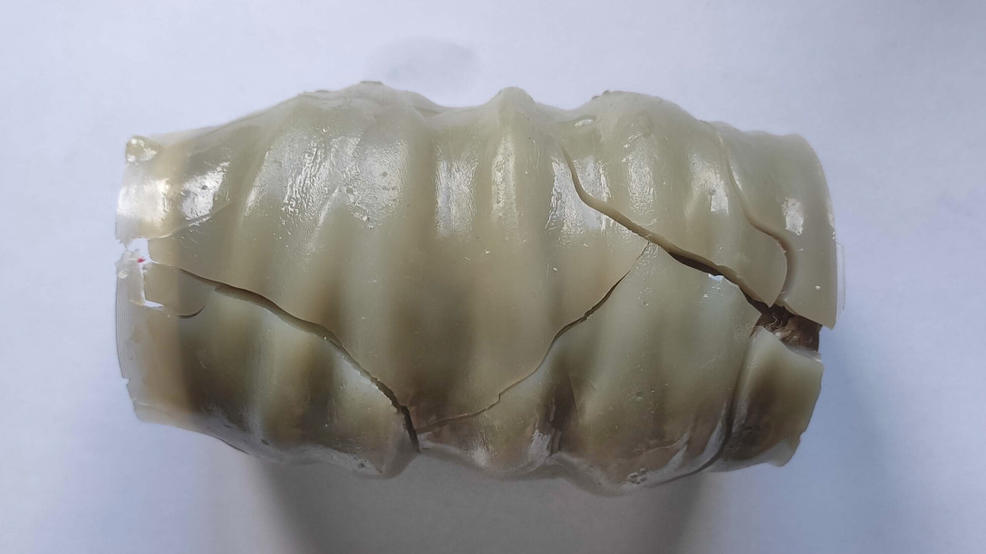
SLA 3D printing with resin typically means rinsing parts with IPA (isopropyl alcohol). That process results in cloudy, used IPA containing a high concentration of dissolved resin. The dual goals of cleaning and reusing IPA are important ones, and we have to say, [Jan Mrázek]’s unusual experiment involving a UV source and slowly-rotating paper tube to extract and cure dissolved resin might look odd, but the results are definitely intriguing.
Dissolved resin successfully pulled from IPA and cured onto a cardboard roll. This particular one rotated a bit too quickly, trapping IPA in the curing process and yielding a slightly rubbery wad instead of a hard solid.
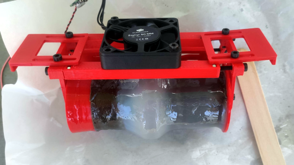
The best way to dispose of liquid resin is to cure it into a solid, therefore making it safe to throw away. But what about resin that has been dissolved into a cleaning liquid like IPA? [Jan] felt that there was surely a way to extract the dissolved resin somehow, which would also leave the IPA clean for re-use. His solution? The device shown here, which uses a cardboard tube to pull dissolved resin from an IPA bath and a UV source to cure it onto the tube.
Here’s how it works: the tube’s bottom third sits in dirty IPA, and UV LEDs shine on the top of the tube. The IPA is agitated with a magnetic stirrer for best results. A motor slowly rotates the cardboard tube; dissolved resin gets on the tube at the bottom, UV cures it at the top, and the whole thing repeats. Thin layers of cured resin slowly build up, and after long enough, the roll of cured resin can be thrown away and the IPA should be clean enough for reuse.
So far it’s a pretty successful test of a concept, but [Jan] points out that there are still some rough edges. Results depend on turning the tube at a good rate; turning it too quickly results in IPA trapped with the cured residue. On the plus side, the UV source doesn’t need to be particularly powerful. [Jan] says that Ideally this would be a device one could run in a sealed container, cleaning it over one or two days.
Resin printing is great, but it’s a messy process, so anything that makes it less wasteful is worth checking out. Got any ideas for improving or building on this concept? If so, don’t keep ’em to yourself! Let us know in the comments.
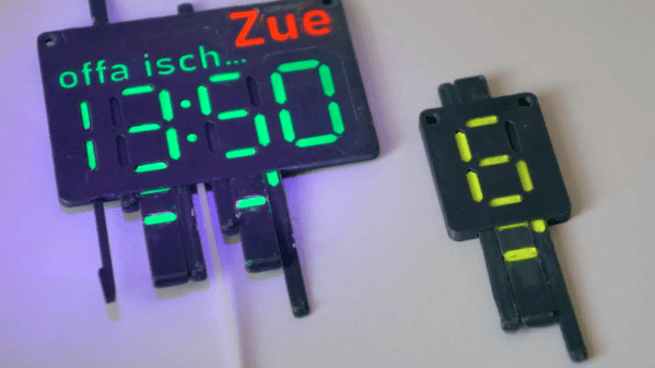
We’ve seen a lot of clever re-imagining of the classic 7-segment display, and proving there is still room for something new is [Jack]’s 7-segment “DigiTag” display.
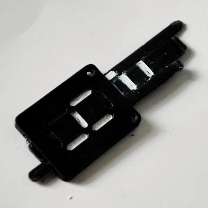
This 3D printable device has a frame into which is slotted three sliders. These sliders can be adjusted individually, mixing and matching the visibility of colored and uncolored areas, to create digits 0-9. We’ve seen some unusual 7-segment-inspired displays before, using from one motor for the whole digit to ones that need one motor per segment, but nothing quite like this approach.
While this particular design relies on the user to manually “dial in” each digit, the resulting key-like assembly (and unique shape for each digit) seems like it could have some interesting applications — a puzzle box design comes to mind.
If you have any ideas of your own on how this could be used, don’t keep them to yourself! Let us know in the comments, below.
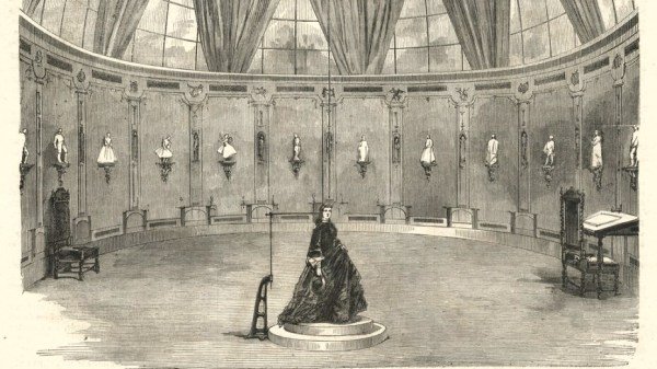
In France during the mid-to-late 1800s, one could go into François Willème’s studio, sit for a photo session consisting of 24 cameras arranged in a circle around the subject, and in a matter of days obtain a photosculpture. A photosculpture was essentially a sculpture representing, with a high degree of exactitude, the photographed subject. The kicker was that it was both much faster and far cheaper than traditional sculpting, and the process was remarkably similar in principle to 3D scanning. Not bad for well over a century ago.
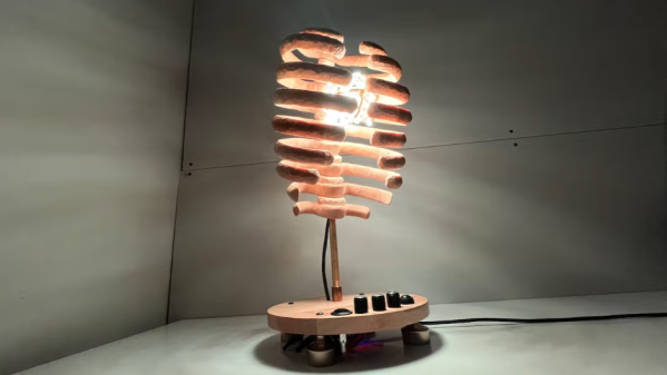
We think [Michelle]’s sound-reactive rib cage lamp turned out great, and the photos and details around how it was made are equally fantastic. The lamp is made of carved and waxed wood, and inside is a bundle of LED lighting capable of a variety of different color palettes and patterns, including the ability to react to sound. Every rib cage should have a party mode, after all.
The LED strip is fashioned into an atom-like structure.
Turns out that designing good rib cage pieces is a bigger challenge than one might think. [Michelle]’s method was to use an anatomical 3D model as reference, tracing each piece so that it could be cut from a flat sheet of wood.
The resulting flat pieces then get assembled into a stack, with each rib pointed downward at a roughly 20 degree angle. This process is a neat hack in itself: instead of drilling holes all at exactly the same angle, [Michelle] simply made the holes twice the diameter of the steel rod they stack on. The result? The pieces angle downward on their own.
The LED lighting is itself a nice piece of work. The basic structure comes from soldered solid-core wire. The RGB LED strip gets wound around that, then reinforced with garden wire. The result is an atomic-looking structure that sits inside the rib cage. An ESP32 development board drives everything with the FastLED library.
Code for everything, including the sound-reactive worky bits, which rely on an INMP441 I2C microphone module is all available on GitHub. And if you want to make your own sound-reactive art, make sure to check out these arms as well.
Want to see the rib cage in action? A short demo video is embedded below that demonstrates the sound reactivity. Equally applicable to either party or relaxation modes, we think.
There are plenty of resins advertised as being suitable for functional applications and parts, but which is best and for what purpose?
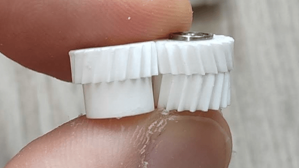
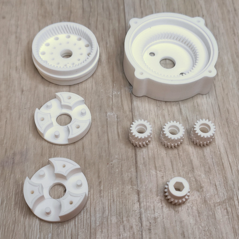
According to [Jan Mrázek], if one is printing gears, then they are definitely not all the same. He recently got fantastic results with Siraya Tech Fast Mecha, a composite resin that contains a filler to improve its properties, and he has plenty of pictures and data to share.
[Jan] has identified some key features that are important for functional parts like gears. Dimensional accuracy is important, there should be low surface friction on mating surfaces, and the printed objects should be durable. Of course, nothing beats a good real-world test. [Jan] puts the resin to work with his favorite method: printing out a 1:85 compound planetary gearbox, and testing it to failure.
The results? The composite resin performed admirably, and somewhat to his surprise, the teeth on the little gears showed no signs of wear. We recommend checking out the results on his page. [Jan] has used the same process to test many different materials, and it’s always updated with all tests he has done to date.