It’s said that slow internet is worse than no internet at all, which is mainly a matter of continuously crushing all hope and sanity vs. finding peace in accepting a fate out of your control. Plus, you can easily pass the time of being catapulted back to the prehistoric ages by navigating a jumpy little creature from that same age through a field of cacti — at least if you’re using Chrome or Chromium. But neither a browser nor actually an operating system are really necessary for that, as [franeklubi] shows with a boot sector implementation of the same game.
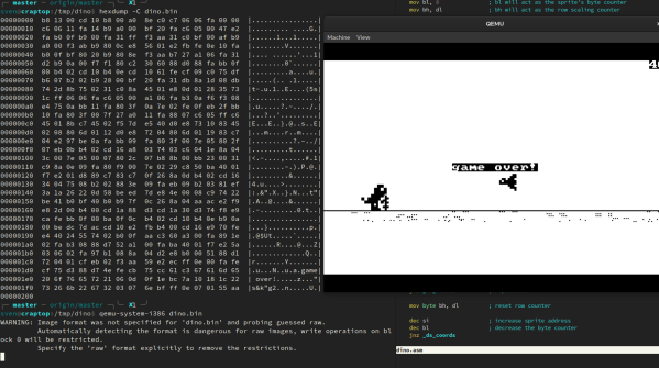
Sure, the graphics aren’t quite on par, but compared to the original’s 3000+ lines of JavaScript, [franeklubi] managed to implement it in a few hundred lines of assembly, and was of course constrained by the 512 bytes of the boot sector itself (well, 510 plus the signature). This constraint causes a few limitations, like a slight lack of randomness in the obstacle arrangements, and a constant running speed, but it also makes it the perfect playground and starting point to delve into the world of nifty knacks and hacks, trying to squeeze every last byte.
If you want to give it a try for yourself, all you need is NASM and QEMU — and while you’re at it, why not have some Tetris along the way? We could also see this nicely combined with the real-world jumping version from a few weeks back, and turn it into a standalone arcade game. Bounce Crouch Revolution anyone?