Replacement PCB Replicates Early 80s Modem

It’s certainly been a few decades, but plenty of us remember a time before widespread access to broadband internet, when connections were generally made over phone lines using acoustic modems. In the 90s these could connect you to AOL and Napster well enough, but in the early 80s the speeds were barely enough to read text as it loaded. A company called Hayes set out to change this with some of the first useful, widely-available modems for the PCs at the time. While they couldn’t keep up with the changing times there’s still a retro community that has these antiques, and to modernize it a bit this drop-in replacement for the PCBs replicates these old modems almost exactly.

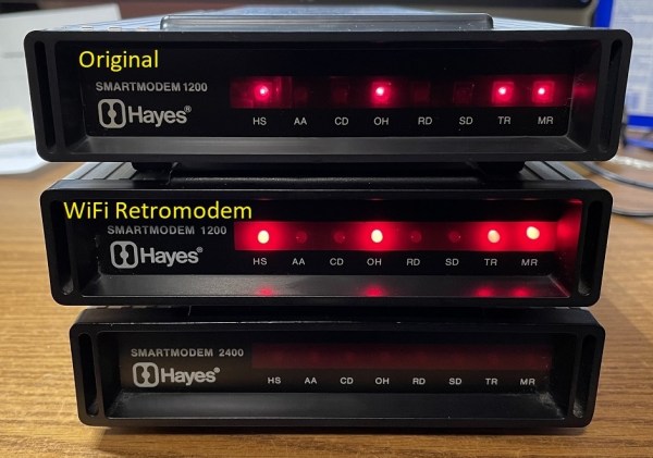
The new PCB is equipped with everything needed to get a retro computer online again, including all the ports to connect a computer without any further modifications. It houses a few modern upgrades beyond its on-board processors, though. Rather than needing an actual acoustic coupled phone, this one has an ESP32 which gives it wireless capability. But the replacement PCB maintains the look and feel of the original hardware by replicating the red status LEDs at the front, fitting into the original Hayes cases with no modifications needed at all, and even includes a small speaker through which it can replicate the various tones, handshakes, and other audio cues that those of us nostalgic for this new online era remember quite well.

For those looking for a retro feel without the hassle of getting antique networking equipment functional again, this type of upgrade that preserves the essence of the original hardware is an excellent way of keeping retro computers functional on modern networking equipment. But if you absolutely must get the networking equipment exactly right down to the last patch cable, you might end up having to build your own ISP from scratch.

Continue reading “Replacement PCB Replicates Early 80s Modem”

Mapping The Nintendo Switch PCB

As electronics have advanced, they’ve not only gotten more powerful but smaller as well. This size is great for portability and speed but can make things like repair more inaccessible to those of us with only a simple soldering iron. Even simply figuring out what modern PCBs do is beyond most of our abilities due to the shrinking sizes. Thankfully, however, [μSoldering] has spent their career around state-of-the-art soldering equipment working on intricate PCBs with tiny surface-mount components and was just the person to document a complete netlist of the Nintendo Switch through meticulous testing, a special camera, and the use of a lot of very small wires.

The first part of reverse-engineering the Switch is to generate images of the PCBs. These images are taken at an astonishing 6,000 PPI and as a result are incredibly large files. But with that level of detail the process starts to come together. A special piece of software is used from there that allows point-and-click on the images to start to piece the puzzle together, and with an idea of where everything goes the build moves into the physical world.

[μSoldering] removes all of the parts on the PCBs with hot air and then meticulously wires them back up using a custom PCB that allows each connection to be wired up and checked one-by-one. With everything working the way it is meant to, a completed netlist documenting every single connection on the Switch hardware can finally be assembled.

The final documentation includes over two thousand photos and almost as many individual wires with over 30,000 solder joints. It’s an impressive body of work that [μSoldering] hopes will help others working with this hardware while at the same time keeping their specialized skills up-to-date. We also have fairly extensive documentation about some of the Switch’s on-board chips as well, further expanding our body of knowledge on how these gaming consoles work and how they’re put together.

PC AT mainboard with both 16-bit ISA and 32-bit PCI slots. (Credit: htomari, Flickr)

How Intel Gave Us The PCI Bus While Burying VESA’s VL-Bus

Gigabyte GA486IM mainboard from 1994 with ISA, VLB and PCI slots. (Credit: Rjluna2, Wikimedia)

The early days of home computing were quite a jungle of different standards and convoluted solutions to make one piece of hardware work on as many different platforms as possible. IBM’s PC was an unexpected shift here, as with its expansion card-based system (retroactively called the ISA bus) it inspired a new evolution in computers. Of course, by the early 1990s the ISA bus couldn’t keep up with hardware demands, and a successor was needed. Many expected this to be VESA’s VLB, but as [Ernie Smith] regales us in a recent article in Tedium, Intel came out of left field with its PCI standard after initially backing VLB.

IBM, of course, wanted to see its own proprietary MCA standard used, while VLB was an open standard. One big issue with VLB is that it isn’t a new bus as such, but rather an additional slot tacked onto the existing ISA bus, as it was then called. While the reasoning for PCI was sound, with it being a compact, 32-bit (also 64-bit) design with plug and play and more complex but also more powerful PCI controller, its announcement came right before VLB was supposed to be announced.

Although there was some worry that having both VLB and PCI in the market competing would be bad, ultimately few mainboards ended up supporting VLB, and VLB quietly vanished. Later on PCI was extended into the Accelerated Graphics Port (AGP) that enabled the GPU revolution of the late 90s and still coexists with its PCIe successor. We covered making your own ISA and PCI cards a while ago, which shows that although PCI is more complex than ISA, it’s still well within the reach of today’s hobbyist, unlike PCIe which ramps up the hardware requirements.

Top image: PC AT mainboard with both 16-bit ISA and 32-bit PCI slots. (Credit: htomari, Flickr)

Harbor Freight And LEGO PCB Vise Is Cheap And Effective

It doesn’t take much chasing things around the bench with a soldering iron to appreciate the value of good work holding. And don’t get us started on those cheap “helping hands” alligator clip thingies; they’re somehow worse than no work holding. Isn’t there a better way?

Maybe, judging by [Paul Bryson]’s idea for a dirt cheap PCB vise. It’s a pretty clever design that’ll have you heading to Harbor Freight, or whatever the moral equivalent is in your location, where you’ll pick up a small ratcheting bar clamp. [Paul] used a 4″ (10 cm) clamp; that which looks fine for a wide range of boards, but we suppose you could go bigger if you like. You could also stop there and just clamp your PCBs in the plastic jaws, but [Paul] adorned the jaws with swiveling arms made from LEGO Technic pieces, of all things. Rubber grommets slipped onto Technic pegs go into the holes on the beam to hold the PCB edges firmly, while the swiveling action adapts to odd-shaped boards.

To our mind, the biggest advantage to this design other than cost is how low it holds the PCB — a decided advantage while working under the microscope. Don’t have any Technics parts close to hand? No worries, 3D printed parts could easily stand in, and maybe even improve the design. [Paul] also shows off a substitute for the Technics beam rendered in PCB material, which would reduce the height of the workpiece over the bench even more.

We’ve seen a lot of PCB vises come and go, using everything from scrap wood to 3D printed compliant mechanisms. But we doubt you’ll find anything more cost-effective than [Paul]’s design.

Fail Of The Week: PCB LED Cube Fails Successfully

Remember LED cubes? We sure do — they were all the rage for a while, and then it seemed like everyone just sort of lost interest in them. There are probably a lot of reasons for that, not least of which is likely the amount of work it takes to put one together from discrete LEDs and separate pieces of wire. Could there be a better way?

Of course there could, and [Sasa Karanovic] thought he had it all figured out with this PCB-based LED cube. At first glance, it seems to make perfect sense; after all, weren’t PCBs invented to take the place of all that pesky point-to-point wiring in the early days of electronics? The boards [Sasa] designed are pretty cool, actually. They’ve each got room for 16 addressable WS2812 LEDs in 5 mm packages, with every possible bit of substrate removed to block the minimum amount of light. That left very little room for traces on the 2-mm-wide arms, so the PCBs had to have four layers, which raised eyebrows at the PCB house when [Sasa] submitted the design.

Such an airy and open design obviously has the potential for mechanical issues, which [Sasa] addressed by adding pads at three corners of each board; a vertical PCB connects to each LED board to provide mechanical support and distribute signals to the LEDs. The cube seems solid enough as a result, and even when handled the LED boards don’t really flop around too much. See the cube in action in the video below.

What’s nice about this design is the perfect spacing between the LEDs in all three dimensions, and the way everything lines up nice and straight. That would be really hard to do with wire, even for the most practiced of circuit sculptors. [Sasa] seems to agree, but still deems the build a failure because the PCBs block too much of the view. We suppose he’s got a point, and we’re not sure how well this would scale to an 8×8 cube. We’re not sure how we’d feel about paying for PCBs that are mostly air either, but as failures go, this one still manages to be pretty successful. Continue reading “Fail Of The Week: PCB LED Cube Fails Successfully”

Cheap Hack Gets PCI-X Card Working In PCI Slot

PCI and PCI-X are not directly compatible, and you’d be forgiven for thinking that means you’re out of luck if you need to use a PCI-X card in a machine that only has basic PCI slots. And yet, that needn’t be the case. As [Peter] shows us, you can work around this with a cheap hacky hack. Our favorite kind!

[Peter] had a PCI-X RAID card that he wanted to use on his Socket 7-based computer. The 3ware 9550SX PCI-X card is 3.3 V only, and doesn’t fit in a typical PCI slot. It’s not compatible mechanically or electrically. Enter a PCI-X riser, which gets around the missing notch that would normally not let the card sit in the slot. Other than that, it just took masking off some pins to avoid damage from the 5 V rail. Throughput is good, too, reportedly sitting at roughly 60-70 MB/s.

The hard part is probably finding a PCI-X riser; PCI-Express stuff is far more common. Few of us need to deal with PCI-X anymore, but if you’re working on some ancient industrial hardware or something, this hack might just save your beans from the roast pot one day.

Continue reading “Cheap Hack Gets PCI-X Card Working In PCI Slot”

High Caliber Engineering On A Low Torque PCB Servo Motor

Building a 3D motor printed motor is one thing, but creating a completely custom servo motor with encoder requires some significant engineering. In the video after the break [365 Robots] takes us through the build process of a closed-loop motor with a custom optical encoder.

The motor, an axial flux design, uses a stack of 0.2mm PCBs with wedge shaped coils clamped in a 3D printed body. It’s similar to some of the other PCB motors we’ve featured, but what really sets this build apart is its custom optical encoder, which was a project in its own right. The 4-bit absolute position encoder uses IR LEDs to shine through an PCB disc with concentric gray code copper encoder rings onto IR receivers. This works because FR4, the composite material used in PCBs doesn’t block IR light.

The motor’s body was printed from ABS to withstand the heat during operation. [365 Robots] didn’t skimp on the testing either, creating a 3D printed closed-loop test stand with load cell and Arduino. Like other PCB motors it produces very little torque, roughly 2% of a typical NEMA17 stepper motor. Even so, the engineering behind this project remains impressive.

Continue reading “High Caliber Engineering On A Low Torque PCB Servo Motor”