The Valve Index VR headset has been around for a few years now. It doesn’t come with eye or face tracking, but that didn’t stop inspired folks like [Physics-Dude] from adding DIY solutions in elegant and effective ways using a combination of hardware, open software, and 3D printable parts.
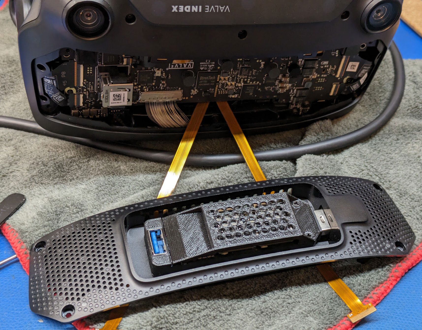
The whole assembly integrates tightly, thanks in part to the “frunk” designed into the Index for exactly this kind of thing.
This project leverages the EyeTrackVR project (and optionally, Project Babble for mouth tracking) which both have great applications particularly in social VR spaces.
These are open-source, self-contained and modular solutions intended for a variety of hardware platforms. Of course, every millimeter and gram tends to count when it’s something that gets worn on one’s head, so [Physics-Dude] tailored a solution specifically for the Valve Index. His project makes great use of the platform’s hacker-friendly hardware design.
[Physics-Dude] also makes excellent use of a certain widely-available “gumstick” style USB hub as an important part of his build. Combined with with the front-mounted USB port on the Index, it results in an extremely compact and tightly integrated solution that looks great. While it can be risky to rely on a particular off-the-shelf item in a build, doing so absolutely has its place here.
The documentation is fantastic, including welcome guidance on cable routing and step-by-step instructions. If you’ve been interested in adding eye tracking to a project, be sure to give it a look. Already have eye tracking in a project of your own? Tell us all about it!
In the 1960s, if you were a teenager in the United States, a big part of your life was probably music. There was a seemingly endless supply of both radio stations and 45s to keep you entertained. In the UK and other countries, though, the government held a monopoly on broadcasting, and they were not always enthralled with the music kids liked. Where there is demand, there is an opportunity, and several enterprising broadcasters set up radio stations at sea, the so-called pirate radio stations. In 1964, Irish businessman [Ronan O’Rahilly] did just this and founded Radio Caroline. Can you imagine that 60 years later, Radio Caroline is still around?
Not that it has been in operation for 60 years in a row. There were a few years the station’s ship had been impounded by creditors. Then, the ship ran aground on the Goodwin Sands and was damaged. You can see a news short from 1965 in the video below (Radio Caroline shows up at about the 1:50 mark).
If there was one question we heard most often this week, it was “Did you see it?” With “it” referring to the stunning display of aurora borealis — and australis, we assume — on and off for several days. The major outburst here in North America was actually late last week, with aurora extending as far south as Puerto Rico on the night of the tenth. We here in North Idaho were well-situated for prime viewing, but alas, light pollution made things a bit tame without a short drive from the city lights. Totally worth it:
Hat tip to Tom Maloney for the pics. That last one is very reminiscent of what we saw back in 1989 with the geomagnetic storm that knocked Québec’s grid offline, except then the colors were shifted much more toward the red end of the spectrum back then.
Even though not all of us will do it, many of us are interested in the art of casting metal. It remains a process that’s not out of reach, though, especially for metals such as aluminium whose melting points are reachable with a gas flame. The video below the break takes us through the aluminium casting process by showing us the lost-foam casting of a cylinder head for a BSA Bantam motorcycle.
The foam pattern is CNC milled to shape, and the leftover foam swarf is removed with a hot wire. The pattern is coated with a refractory coating of gypsum slurry, and the whole is set up in a tub packed with sand. We get the impression that the escaping gasses make this a tricky pour without an extra sprue, and indeed, they rate it as not perfect. The cooling fins on the final head are a little ragged, so it won’t be the part that goes on a bike, but we can see with a bit of refining, this process could deliver very good results.
For this pour, they use a gas furnace, but we’ve seen it done with a microwave oven. Usually, you are losing wax, not foam, but the idea is the same.
We always think of [Scott Manley] as someone who knows a lot about rockets. So, if you think about it, it isn’t surprising he’s talking about GPS — after all, the system uses satellites. GPS is used in everything these days, and other forms of navigation are starting to fall by the wayside. However, the problem is that the system is vulnerable to jamming and spoofing. This is especially important if you fear GPS allowing missiles or drones to strike precise targets. But there are also plenty of opportunities for malicious acts. For example, drone light shows may be subject to GPS attacks from rival companies, and you can easily imagine worse. [Scott] talks about the issues around GPS spoofing in the video, which you can see below.
Since GPS satellites are distant, blocking the signal is almost too easy, sometimes happening inadvertently. GPS has technology to operate in the face of noise and interference, but there’s no way to prevent it entirely. Spoofing — where you produce false GPS coordinates — is much more difficult.
As desktop 3D printers have inched towards something resembling the mainstream, manufacturers have upped their game across the board. Even the quality of filament that you can get today is far better than what was on the market in the olden days, back when a printer made out of laser-cut birch wasn’t an uncommon sight at the local makerspace. Now, even the cheap rolls are wound fairly well and are of a consistent diameter. For most folks, you just need to pick a well-reviewed brand, buy a roll, and get printing.
But as with everything else, there are exceptions. Some people are producing their own filaments, or want to make sure their extrusion rate is perfectly calibrated. For those that need the capability, the WInFiDEL from [Sasa Karanovic] can detect filament diameter in real-time while keeping the cost and complexity as low as possible. Even better, with both the hardware and software released as open source, it makes an excellent starting point for further development and customization.
Although we usually imagine the conditions in Ancient Egypt to be much like the Egypt of today, back during the Holocene there was significantly more rain as a result of the African Humid Period (AHP). This translated in the river Nile stretching far beyond its current range, with many more branches. This knowledge led a team of researchers to test the hypothesis that the largest cluster of pyramids in the Nile Valley was sited along one of these now long since vanished branches. Their findings are described in an article published in Communications Earth & Environment, by [Eman Ghoneim] and colleagues.
The Ahramat Branch and pyramids along its trajectory. (Credit: Eman Ghoneim et al., 2024)
The CliffsNotes version can be found in the accompanying press release by the University of North Carolina Wilmington. Effectively, the researchers postulated that a branch of the Nile existed along these grouping of pyramids, with their accompanying temples originally positioned alongside this branch. The trick was to prove that a river branch once existed in that area many thousands of years ago.
What complicates this is that the main course of the Nile has shifted over the centuries, and anthropogenic activity has obscured much what remained, making life for researchers exceedingly difficult. Ultimately a combination of soil core samples, geophysical evidence, and remote sensing (e.g. satellite imagery) helped to cement the evidence for the existence what they termed the Ahramat Nile Branch, with ‘ahramat’ meaning ‘pyramids’ in Arabic.
Synthetic Aperture Radar (SAR) and high-resolution radar elevation data provided evidence for the Nile once having traveled right past this string of pyramids, also identifying the modern Bahr el-Libeini canal as one of the last remnants of the Ahramat Branch before the river’s course across the floodplain shifted towards the East, probably due to tectonic activity. Further research using Ground Penetrating Radar (GPR) and Electromagnetic Tomography (EMT) along a 1.2 km section of the suspected former riverbed gave clear indications of a well-preserved river channel, with the expected silt and sediments.
Soil cores to a depth of 20 and 13 meters further confirmed this, showing not only the sediment, but also freshwater mussel shells at 6 meter depth. Shallow groundwater was indicated at these core sites, meaning that even today subsurface water still flows through this part of the floodplain.
These findings not only align with the string of pyramids and their causeways that would have provided direct access to the water’s edge, but also provided hints for a further discovery regarding the Bent Pyramid — as it’s commonly known — which is located deep inside the desert today. Although located far from the floodplain by about a kilometer, its approximately 700 meters long causeway terminates at what would have been a now extinct channel: the Dahshur Inlet, which might also have served the Red Pyramid and others, although evidence for this is shakier.
Altogether, these findings further illustrate an Ancient Egypt where the Old Kingdom was followed by a period of severe changes, with increasing drought caused by the end of the AHP, an eastwardly migrating floodplain and decreased flow in the Nile from its tributaries. By the time that European explorers laid eyes on the ancient wonders of the Ancient Egyptian pyramids, the civilization that had birthed them was no more, nor was the green and relatively lush environment that had once surrounded it.