Easy Blinking LED Eyes For Halloween

There’s not much time left now. If you’re going to put something together to give the youngsters some night terrors in exchange for all that sweet candy, you better do it quick. This late to the game you might not have time to do anything too elaborate, but luckily we’ve come across a few quick Halloween hacks that can get you some pretty cool effects even if it’s only a few hours before the big night.

As a perfect example, these LED “blinking eyes” were created by [Will Moser]. Using nothing more exotic than some bare LEDs, an Arduino, and a cardboard box, these little gadgets can quickly and easily be deployed in your windows or bushes to produce an unsettling effect after the sun goes down. Thanks to the pseudorandom number generator in the Arduino code, the “eyes” even have a bit of variability to them, which helps sell the idea that your Halloween visitors are being watched by proper creatures of the night.

The hardware side of this project is very simple. [Will] takes a container such as a small cardboard box and cuts two holes in it to serve as the eyes. He notes that containers which are white or reflective on the inside work best. You’ll want to get a little artistic here and come up with a few different shaped sets of eyes, which is demonstrated in the video after the break. Inside each box goes a colored LED, wired back to the Arduino.

For the software, [Will] is using a floating analog pin as a source of random noise, and from there comes up with how often each LED will blink on and off, and for how long. Both the hardware and software sides of this project are perfect for beginners, so it might be a good way to get the Little Hackers involved in the festivities this year; if you’re the type of person who enjoys replicating small humans in addition to creeping them out.

LEDs seem to be the hacker’s decoration of choice come Halloween, from wearable LED eyes to remote controlled illuminated pumpkins.

Continue reading “Easy Blinking LED Eyes For Halloween”

Custom LED Signage From Household Items

We’ll admit it: sometimes we overthink things. We imagine some of you are the same way; there seems to be something in the hacker mentality that drives us to occasionally over-engineer ideas to the point of unrecognizability. There’s nothing inherently wrong with this, but sometimes it does keep us from seeing easier solutions.

For example, the very slick looking personalized LED sign (Google Translate) that [Clovis Fritzen] recently wrote in to share with us. If we were tasked with creating something like this there would certainly have been a 3D printer and likely a CNC involved before all was said and done, and a few days later we’d still be working out the bugs in our OpenSCAD code. But his approach is very different. Fantastically simple and constructed largely from household items, this is a good project to keep the Junior Hackers entertained on a rainy weekend.

The first step of the process is to draw out the characters you want onto a piece of cardboard, and then carefully cut it out. If you’re worried that you’re not particularly artistic, this step will go a bit better if you print out the design and tape the paper over the cardboard to serve as a template. Once you’ve got your design cut out, you glue or tape a piece of standard printer paper over it. This is the face of the display; it just needs to be lit from behind.

If you wanted to make a sign that was just a single color and didn’t have individually addressable elements, then it would be enough to illuminate the whole cutout with a single light source. But where’s the appeal in that? As [Clovis] shows, you can get much better results by constructing a segmented box, with one LED in each cell. By wiring each LED to a pin on an Arduino or other microcontroller, you’ll have control over the color and brightness of each section of the sign.

Of course, if you’re not big on the whole cardboard aesthetic, you could even recreate this design with the aforementioned CNC and 3D printer. [Clovis] shows how the basic concept works, and that it can be scaled pretty easily depending on the kind of materials you have access to.

Vinduino Water-Smart Farming – Now With LoRa!

Our five rounds of Hackaday Prize 2018 challenges have just wrapped up, and we’re looking forward to see where the chips fall in the final ranking. While we’re waiting for the winners to be announced at Hackaday Superconference, it’s fun to take a look back at one of our past winners. Watch [Reinier van der Lee] give the latest updates on his Vinduino project (video also embedded after the break) to a Hackaday Los Angeles meetup earlier this year.

Vinduino started with [Reinier]’s desire to better understand what happens to irrigation water under the surface, measuring soil moisture at different depths. This knowledge informs more efficient use of irrigation water, as we’ve previously covered in more detail. What [Reinier] has been focused on is improving usability of the system by networking the sensors wirelessly versus having to walk up and physically attach a reader unit.

His thought started the same as ours – put them on WiFi! But adding WiFi coverage across his entire vineyard was not going to be cost-effective. After experimenting with various communication schemes, he has settled on LoRa. Designed to trade raw bandwidth for long range with low power requirements, it is a perfect match for a network of soil moisture sensors.

In the video [Reinier] gives an overview of LoRa for those who might be unfamiliar. Followed by results of his experiments integrating LoRa functionality into Vinduino, and ending with a call to action for hackers to help grow the LoRa network. It sounds like he’s become quite the champion for the cause! He’s even giving a hands-on workshop at Supercon where you can build your own LoRa connected sensor. (Get tickets here.)

We’re always happy to see open-source hardware projects like Vinduino succeed, transitioning to a product that solve real world problems. We know there are even more promising ideas out there, which is why Hackaday’s sister company Tindie is funding a Project to Product program to help this year’s winners follow in Vinduino’s footsteps. We look forward to sharing more success stories yet to come.

Continue reading “Vinduino Water-Smart Farming – Now With LoRa!”

A Robotic Arm For Those Who Like Their Kinematics Both Ways

A robotic arm is an excellent idea if you’re looking to get started with electromechanical projects. There’s linkages to design, and motors to drive, but there’s also the matter of control. This is referred to as “kinematics”, and can be considered in both the forward and inverse sense. [aerdronix] built a robotic arm build that works in both ways.

The brains of the build is an Arduino Yun, which receives commands over the USB interface. Control is realised through the Blynk app, which allows IoT projects to easily build apps for smartphones that can be published to the usual platforms.

The arm’s position is controlled in two fashions. When configured to use inverse kinematics, the user commands an end effector position, and the arm figures out the necessary position of the linkages to make it happen. However, the arm can also be used in a forward kinematics mode, where the individual joint positions are commanded, which then determine the end effector’s final position.

Overall, it’s a well-documented build that lays out everything from the basic mechanical design to the software and source code required to control the system. It’s an excellent learning resource for the newcomer, and such an arm could readily be used in more complex projects.

We see plenty of robotic arms around these parts, like this fantastic build based on an IKEA lamp. If you’ve got one, be sure to hit up the tip line. Video after the break.

Continue reading “A Robotic Arm For Those Who Like Their Kinematics Both Ways”

Just In Time For Halloween: Another Talking Skull

It isn’t a unique idea, but we liked [Eric Wiemers’s] take on the classic animated skull for Halloween. In addition to showing you the code and the wiring, the video spends some time discussing what the audio looks like and what has to happen to get it into a format suitable for the Arduino. You can see the spooky video, below.

Of course, this is also a 3D printing project, although the skull is off-the-shelf. We wondered if he felt like a brain surgeon taking the Dremel to the poor skull. To fix the two parts of the device, he used brass threaded inserts that are heat set, something we’ve seen before, but are always surprised we don’t see more often.

Continue reading “Just In Time For Halloween: Another Talking Skull”

The 3D Printed Plotter You Didn’t Know You Needed

We’ve been seeing an influx of repurposed 3D printers recently. Thrifty hackers have been leveraging cheap 3D printers as a way to bootstrap their builds, on everything from laser engravers to pick and place machines. There’s nothing wrong with that, and honestly when you can get a cheap 3D printer for less than the cost of the components separately thanks to the economies of scale, you’d be foolish not to.

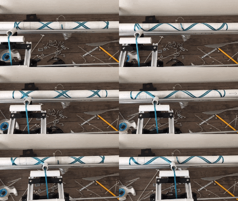
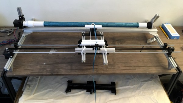
But there’s still something to be said for the classic RepRap mentality of building things using printed parts and smooth rods. Case in point, the largely 3D printed plotter that [darth vader] sent in for our viewing pleasure. This isn’t somebody sicking a pen on the extruder of their open box Monoprice special, this is a purpose built plotter and it shows. In the video after the break you can see not only how well it draws, but also how large of a work area it has compared to a modified 3D printer.

If you know your way around a 3D printer, most of it should look pretty familiar to you. Using the same GT2 belts, steppers, end stop switches, and linear bearings which are ubiquitous in 3D printers, it shouldn’t be difficult to source the parts to build your own. It even uses a Mega 2560 with RAMPS 1.4 running Marlin 1.1.9 for control.

The biggest difference is the physical layout. Since there’s no heavy hotend or extruder assembly to move around, the plotter has a cantilever design which gives it far greater reach. As it only needs to sightly lift the pen off the paper, there’s no need for a complex Z axis with leadscrews either; a simple servo mounted to the end of the arm is used to raise and lift the pen. We especially like the use of a tape measure as strain relief for his wiring, a fantastic tip that we (and many of you) fell in love with last year.

While it’s hard to beat just tossing a pen onto the business end of your desktop 3D printer in terms of convenience, we think it’s pretty clear from this build that the results don’t quite compare. If you want a real plotter, build a real plotter.

Continue reading “The 3D Printed Plotter You Didn’t Know You Needed”

Flash: Arduino Vidor FPGA Instructions Hit France

If you speak French and you have an Arduino Vidor 4000, you are in luck because there’s some good news. The good news is there’s finally some inside information about how to configure the onboard FPGA yourself. The bad news though is that it is pretty sparse. If your high school French isn’t up to the task, there’s always Google Translate.

We knew some of this already. You’ll need Quartus, the FPGA design tool from Altera — er, Intel — and we know about the sample project on GitHub, too. Instead of using conventional Verilog or VHDL, the new information uses schematic capture, but that’s OK. All the design entry winds up in the same place, so it should be easy to adapt to the language of your choice. In fact, in part 2 they show both some schematics and some Verilog. Google Translate does have a little trouble with code comments, though. If you want something even stouter, there’s an example that uses Verilog to output a video frame.

Continue reading “Flash: Arduino Vidor FPGA Instructions Hit France”