Touchscreens are great, but they’re not always the perfect solution. Trying to operate one with gloves on (even alleged “touchscreen-friendly” ones) can be cumbersome at best, and if the screen is on a publicly-shared device, such as a checkout kiosk it can easily become a home for bacteria, viruses and all sorts of other nasty stuff.
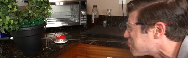
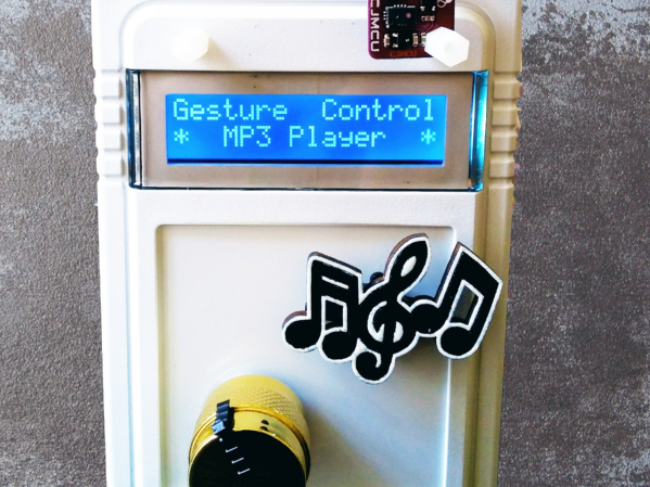
That’s what [Norbert Zare] was thinking when he built his gesture-controlled MP3 player. It uses a PAJ7620U2 gesture sensor to register a few intuitive hand motions including finger twirls to control the volume, hand swipes to skip forward and backwards, and a flat hand to play and pause the song. It even has a motorized knob and cute cutout music notes that move to provide some visual feedback for the gestures, which you can see in-action in the video below. If this seems familiar, it’s because on Tuesday we took a look at the camera-based, glance-to-skip-tracks controller he built.
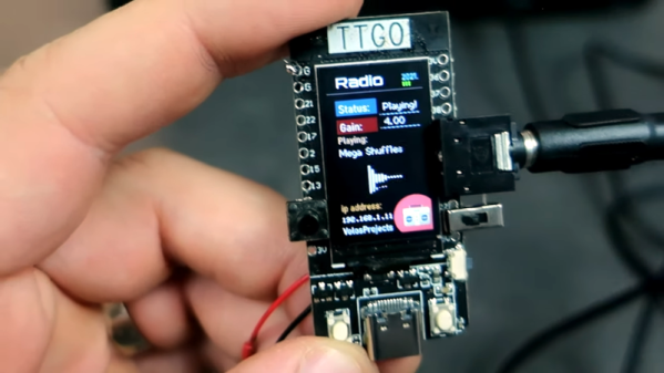
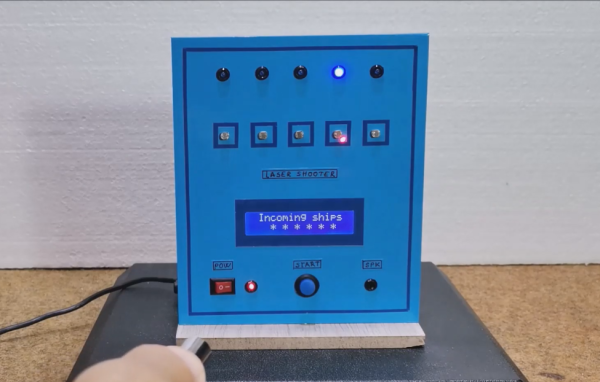
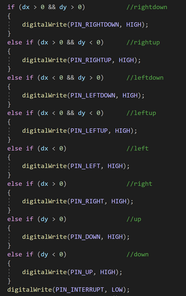
To actually play some music, he gutted an old MP3 player and hooked the solder pads from the control buttons up to an Arduino, which reads gesture information from the sensor and emulates the MP3 player’s buttons by setting the appropriate pins to HIGH and LOW. Finally, he topped the whole thing off with an LCD screen and a case.
The great thing about [Norbert]’s approach is that it isn’t just limited to an MP3 player — it can be extended to replace the buttons on pretty much any device. Because the Arduino only needs to be connected to the button inputs of the device, it should be relatively easy to adapt most existing tactile interfaces to be touch-free. Paired with this gesture-tracking macro keyboard we saw earlier in the year, the days of actually having to touch our tech may soon be behind us.
Continue reading “Groovin’ With A Gesture-Controlled MP3 Player”