Sending An ESP32 Into Space

Just two weeks ago, the crew from the International Space Station released a photo of their nine crew members – an odd number considering that the facility only has space to house six astronauts at a time. In fact, the crew had just gathered for a celebratory dinner before three of the astronauts were to return home. The new astronauts joining including Hazza Al Mansouri, the first astronaut from the United Arab Emirates (who has since returned from his mission), as well as astronaut Jessica Meir and cosmonaut Oleg Skripochka.

Amidst the excitement over the upcoming 10 (!) spacewalks in the next three months, there’s also been some cool developments in the open source space, with one of the first ESP32s launched into space.

[Nico Maas] from the Microgravity User Support Center (MUSC) at DLR (German Aerospace Center) worked on an experiment launched by MORABA (Mobile Rocket Base) at DLR. The launch site was at the Esrange Space Center in Kiruna, Sweden, with the mission launching on June 13, 2019 at 4:21 am local time.

The experiment – APEX (Advanced Processors, Encryption, and Security Experiment) was onboard the ATEK / MAPHEUS-8, mission, rising to an altitude of 240km into space and returning back to earth after six minutes of microgravity.

[via AIP]
The goal of the research was to develop an off-the-shelf computer with a more powerful system for high-speed sensors and image acquisition than the Microchip ATmega328P, the current standard. The flight test measured the speed of the system as well as stress testing its ability to handle compute-intensive tests.

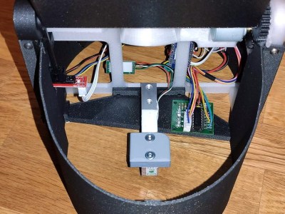
The main board included two ESP32s and a Raspberry Pi Zero W, running resinOS / balenaOS, an operating system designed to run parallel Docker containers and optimized for IoT fleet management.

Prior to the experiment, the standard for on-board computers for use in CubeSats was the ATmega/Arduino-based ARDUSAT. Since it was first made available for use in CubeSats in 2013, the performance has become limited, with improvements needed to perform higher throughput data sampling or operations requiring more computational power.

It’s also cool to note that the system, built using a 3D-printed holder, survived the re-entry (reaching up to 20.6g) with hardly a scratch.

Continue reading “Sending An ESP32 Into Space”

The Next Generation Arduino Nano

While we certainly do love the Arduino Nano for its low-cost and versatility in projects, it’s unarguable that every tools has its gripes. For one maker in particular, there were enough complaints to merit a redesign of the entire board. While Arduino may or may not be interested in incorporating these changes into a redesign of the development board, there is certainly room for a new manufacturer to step in and improve some features.

[Kevin Timmerman] takes a look at lower-cost clones of the Nano made in China to highlight a few interesting key differences that make the clones – cheaper but still compatible with legacy systems – more attractive.

The PCB manufacturing for the Arduino Nano currently places components on both sides of the board, requiring two operations for solder paste, pick-and-place, and reflow. Naturally this increases costs, simply designing a two-layer PCB with components on top lowers the price of manufacturing.

Since the ATmega328PB was released, it has proven to be a better and cheaper MCU for manufacturing than the ATmega328P, the current MCU used by the Arduino Nano and clones. While the newer MCU is not backwards compatible like its predecessor, it has additional UART, GPIO, counters, and other features that allow users to take advantage of new libraries and peripherals.

Rather than featuring the typical voltage regulator used by Arduino boards (used to allow the board to be powered by a voltage source greater than 5V), a switching regulator allows for less energy loss but a higher component cost. A better solution than both of these would be to simply not have a voltage regulator. While this may be controversial, there are sufficient battery power sources for this design to work (4 cells of AA or AAA NiMh batteries or a mobile phone charger).

The Arduino Nano uses a bootloader for handling programming the MCU, which requires the USB to serial bridge to be disconnected from anything that could interfere with the programming. Thus, programs using the COM port on the computer must release the port, including the serial monitor. Rather than using the bootloader, ICSP (in-circuit serial programming) and DebugWire are possible alternatives that connect the ICSP pins to the CH551 development board or programming via the reset pin.

There are a number of other spec and firmware improvements suggested in the writeup, as well as comparison between the Arduino Nano, Arduino Every, and Chinese clones. It’s definitely worth a look!

These Dice Know If You’re Cheating

Fans of D&D are surely aware of the significance of a good pair of dice. What if your dice were not only stylish, but smart? For anyone who’s ever had to deal with playing board games with less than reputable siblings or friends, the electric die just might be your savior.

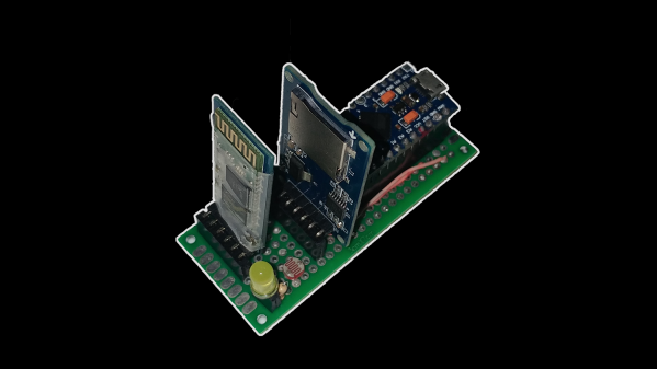
The dice are configured via Bluetooth, tracking rolls and stats over the course of gameplay captured by an accelerometer.

The PCB had to have a flexible surface – specifically in the shape of an unfolded icosahedron – in order to form the shape of the die which constrains the design to two layers. Each face contains an LED facing outwards to light up the number on that side. The LEDs are directly powered by a rechargeable battery, which uses a small coil for wireless inductive charging. Rather than opting for a Qi charger chipset, which regulates the maximum amount of power transmitted if the efficiency falls below a threshold, [Jean Simonet] uses a simpler charger setup using a full bridge rectifier, capacitors, and a linear regulator to create a stable 5V supply for the receiving end.

While the initial design for the die required an injection molded plastic shell, an easier solution was to simply cast the designs in resin. The electronics are placed into a dice mold and cast just as a regular die would be.

This luckily also solved the issue of needing to fit the components inside a screw-on container with a removable lid, which presented a hassle in terms of finding a battery that would fit the dimensions. The LEDs – purchased for cheap on Alibaba – are daisy chained to reduce the complexity of the routing.

One issue with the LEDs, however, is that the internal PWMs modulating the intensity remain on even at an intensity of 0, constantly drawing 21 mA (for the 21 LEDs on the die). This causes the battery to die after 2-3 hours. The solution [Simonet] used was to add a transistor to cut off power to the LEDs and to have the MCU toggle the transistor when the LEDs are turned off. Even this solution didn’t solve the entire problem since the LEDs still drain current from the data and clock lines, so those lines had to be low before going to sleep.

There were some stability issues with using a small buck converter to bring the LiPo voltage down to 3.3V, so the power regulation was done directly by the MCU instead. Switching the die off is controlled by a magnetic switch connected to a power buck converter that turns off logic when a magnet is present. This initially caused the LED control lines to become floating when power was turned off, turning the LEDs to arbitrary colors. The solution was to wire the output of the magnetic sensor to the MCU and to allow the software to handle the LEDs as well.

Maybe it’s because creator [Simonet] happens to be a game developer as well, but the early development stages of the electronic die (CAD, circuit schematics, prototyping, hand soldering components) were streamed on Twitch, adding some interactivity to even the build phase. The end result may be small, but these dice certainly have large brains!

Continue reading “These Dice Know If You’re Cheating”

Captivating Clock Tells Time With Tall Tubes

Time is probably our most important social construct. Our perception of passing time changes with everything we do, and when it comes down to it, time is all we really have. You can choose to use it wisely, or sit back and watch it go by. If you want to do both, build a clock like this one, and spectate in sleek, sophisticated style.

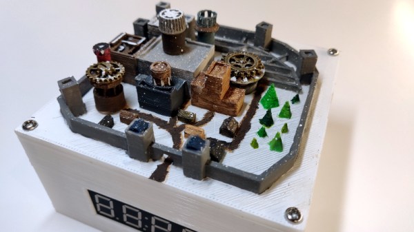
[ChristineNZ]’s mid-century-meets-steampunk clock uses eight ILC1-1/8Ls, which are quite possibly the largest VFD tubes ever produced (and still available as new-old stock). In addition to the time, it displays the date, relative humidity, and temperature in both Celsius and Fahrenheit. A delightful chime sounds every fifteen minutes to remind you that time’s a-wastin’.

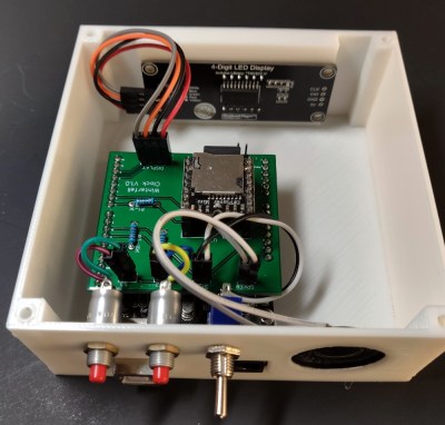
The seconds slip by in HH/MM/SS format, each division separated by a tube dedicated to dancing the time away. The mesmerizing display is driven by an Arduino Mega and a MAX6921 VFD driver, and built into a mahogany frame. There isn’t a single PCB in sight except for the Mega — all the VFDs are mounted on wood and everything is wired point-to-point. Sweep past the break to see the progressive slideshow build video that ends with a demo of all the functions.

Those glowing blue-green displays aren’t limited to clocking time. They can replace LCDs, or be scrolling marquees.

Continue reading “Captivating Clock Tells Time With Tall Tubes”

Making Music From Cardboard

Fans of MaKey MaKey may find this project similar, but there’s a lot more to the Mini Automat than making music from fruit.

The idea for the Mini Automat (which is an off-shoot of the original Automat project by [Dada Machines]) is to make music accessible to anyone. The device functions as a plug and play MIDI-controller that connects to a computer, MIDI workstation (keyboards and sequencers), or DAW for input and triggers actuators on the output to create music.

The modifications make the originally Automat more hackable by making the board compatible with Arduino and Circuit Python, as well as adding in digital and analog pins for connecting to sensors, buttons, or light systems.

The team has released all schematics, firmware, and software, with only the board layouts unreleased to the public. From solenoids that push, pull, jiggle, smash, and bash at drums to surfaces that vibrate screws and beads, there’s a huge variety of household objects that can be used to make complex layered musical compositions, even for a one-person musician.


The Berlin-based team works on open source music tech hardware with the hopes of bringing environmentally and financially sustainable ideas to market.

Continue reading “Making Music From Cardboard”

Introducing The First Cisco Certified Mixologist

You’d be hard pressed to find an IT back office that doesn’t have a few Cisco routers or switches laying around and collecting dust. We’d even bet there are a decent number of people reading this post right now that have a stack of them within arm’s reach. They’re the kind of thing most of us have no practical application for, but we still can’t bear to throw away. But it looks like [Sven Tantau] has found an ideal middle ground: rather than junk his Cisco Catalyst switches, he turned them into automatic bartenders.

Inspired by all those perfect little square openings on the front, [Sven] loaded each switch with a whopping 24 peristaltic pumps, one for each Ethernet port. To fit all his plumbing inside, the switches were naturally gutted to the point of being hollow shells of their former selves, although he does mention that their original power supplies proved useful for keeping two dozen power-hungry motors well fed.

The motors are connected to banks of relays, which in turn are thrown by an ESP32 and an Arduino Nano. [Sven] explains that he wasn’t sure if the ESP32 could fire off the relays with its 3 V output, so he decided to just use an Arduino which he already knew could handle the task. The two microcontrollers work in conjunction, with a web interface on the ESP32 ultimately sending I2C commands to the Arduino when it’s time to get the pumps spinning.

[Sven] mentions his robotic bartenders were a hit at the 2019 Chaos Communication Camp, where we know for a fact the computer-controlled alcohol was flowing freely. Of course, if you don’t intend on carrying your barbot around to hacker camps, you can afford to make it look a bit swankier.

Continue reading “Introducing The First Cisco Certified Mixologist”

No Need To Watch Your Tea, This Robot Does It For You

For anyone who’s ever had to make their own tea, steeping it for the right amount of time can be a pain. That’s precisely the problem that the automatic tea brewing robot solves with its painless approach to brewing tea, built by Slovenian electrical engineering student [Kristjan Berce].

You can use the robot by setting a timer on the knob, at which point the robot raises it arm for the tea bag then dips in the water every 30 seconds until the time has passed. At the end of the timer, the bag is raised clear of the cup to end the brewing. It’s a remarkably simple design that almost evokes chindogu (the Japanese art of useless inventions) if not for the fact that the robot actually serves a useful purpose.

The components for 3D printing the robot are available online, consisting of a case, a container for the Arduino-powered electronics, the lever for holding the tea, and the gear that raises the lever up and down. The device also uses an integrated Li-Ion battery with an accessible charging port and integrated BMS. A 35BYJ46 stepper motor and ULN2003 driver are used to move the 3D printed mechanism. The device uses a potentiometer for setting the steeping time between 1 and 9 minutes, and there’s even a buzzer for indicating once the tea is done brewing.

The Gerber and Arduino code files are open-source for any hackers looking to make their own tea brewers; just take care they operate with “deadly punctuality”.

Continue reading “No Need To Watch Your Tea, This Robot Does It For You”