My introduction to circuit protection came at the tender age of eight. Being a curious lad with an inventive – and apparently self-destructive – bent, I decided to make my mother a lamp. I put a hose clamp around the base of a small light bulb, stripped the insulation off an old extension cord, and jammed both ends of the wires under the clamp. When I plugged my invention into an outlet in the den, I saw the insulation flash off the cord just before the whole house went dark. Somehow the circuit breaker on the branch circuit failed and I tripped the main breaker on a 200 amp panel. My mother has never been anywhere near as impressed with this feat as I was, especially now that I know a little bit more about how electricity works and how close to I came to being a Darwin Award laureate.
To help you avoid a similar fate, I’d like to take you on a trip (tee-hee!) through the typical household power panel and look at some of the devices that stand at the ready every day, waiting for a chance to save us from ourselves. As a North American, I’ll be focusing on the residential power system standards most common around here. And although there is a lot of technology that’s designed to keep you safe as a last resort, the electricity in your wall can still kill you. Don’t become casual with mains current!
We’ve all taken apart a small toy and pulled out one of those little can motors. “With this! I can do anything!” we proclaim as we hold it aloft. Ten minutes later, after we’ve made it spin a few times, it goes into the drawer never to be seen again.
It’s all their fault
It always seems like they are in everything but getting them to function usefully in a project is a fool’s errand. What the heck are they for? Where do people learn the black magic needed to make them function? It’s easy enough to pull out the specification sheet for them. Most of them are made by or are made to imitate motors from the Mabuchi Motor Corporation of Japan. That company alone is responsible for over 1.5 billion tiny motors a year.
More than Just the Specs
In the specs, you’ll find things like running speed, voltage, stall current, and stall torque. But they offer anything but a convincing application guide, or a basic set of assumptions an engineer should make before using one. This is by no means a complete list, and a skip over the electrics nearly completely as that aspect of DC motors in unreasonably well documented.
The paint mixers high running speed and infrequent use make it a decent candidate for hooking directly to the motor.
The first thing to note is that they really aren’t meant to drive anything directly. They are meant to be isolated from the actual driving by a gear train. This is for a lot of reasons. The first is that they typically spin very fast, 6,000 – 15,000 rpm is not atypical for even the tiniest motor. So even though the datasheet may throw out something impressive like it being a 3 watt motor, it’s not exactly true. Rather, it’s 3 N*m/s per 15,000 rotations per minute motor. Or a mere 1.2 milliwatt per rotation, which is an odd sort of unit that I’m just using for demonstration, but it gives you the feeling that there’s not a ton of “oomph” available. However, if you start to combine lots of rotations together using a gear train, you can start to get some real power out of it, even with the friction losses.
The only consumer items I can think of that regularly break this rule are very cheap children’s toys, which aren’t designed to last long anyway, and those powered erasers and coffee stirrers. Both of these are taking for granted that their torque needs are low and their speed needs are high, or that the motor burning out is no real loss for the world (at least in the short term).
This is because the motors derate nearly instantly. Most of these motors are hundreds of loops of very thin enameled wire wrapped around some silicon steel plates spot welded or otherwise coerced together. This means that even a small heat event of a few milliseconds could be enough to burn through the 10 micrometer thick coating insulating the coils from each other. Practically speaking, if you stall a little motor a few times in a row you might as well throw it away, because there’s no guessing what its actual performance rating is anymore. Likewise, consistently difficult start-ups, over voltage, over current, and other abuse can quickly ruin the motor. Because the energy it produces is meant to spread over lots of rotations, the motor is simply not designed (nor could it be reasonably built) to produce it all in one dramatic push.
Making Contact
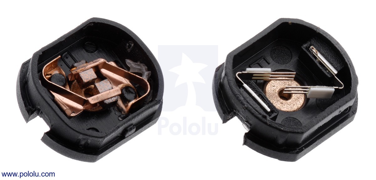
Pololu has the clearest picture of the different kind of brushes inside these small motors.
This brings me to another small note about these tiny motors. Most of them don’t have the carbon brushes one begins to expect from the more powerful motors. Mostly they have a strip of copper that’s been stamped to have a few fingers pressing against the commutator. There’s lots of pros to these metal contacts and it’s not all cost cutting, but unless you have managed to read “Electrical Contacts” by Ragnar Holm and actually understood it, they’re hard to explain. There’s all sorts of magic. For example, just forming the right kind of oxide film on the surface of the commutator is a battle all on its own.
It’s a weird trade off. You can make the motor cheaper with the metal contacts, for one. Metal contacts also have much lower friction than carbon or graphite brushes. They’re quieter, and they also transfer less current, which may seem like a bad thing, but if you have a stalled motor with hairlike strands transferring the pixies around the last thing you’d want to do is transfer as much current as possible through them. However, a paper thin sheet of copper is not going to last very long either.
So it comes down to this, at least as I understand it: if bursts of very fast, low energy, high efficiency motion is all that’s required of the motor over its operational life then the metal strip brushes are perfect. If you need to run the motor for a long stretches at a time and noise isn’t an issue then the carbon brush version will work, just don’t stall it. It will cost a little bit more.
Take Care of Your Tiny Motors
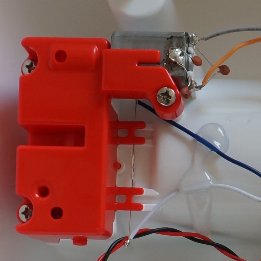
Here is one of these motors being restrained properly. Only torque on the case is restrained. The motor is otherwise free to move.
To touch one other small mechanical consideration. They are not designed to take any axial load at all, or really even any radial load either. Most of them have a plastic or aluminum bronze bushing, press-fit into a simple stamped steel body. So if you design a gearbox for one of these be sure to put as little force as possible on the bearing surfaces. If you’ve ever taken apart a small toy you’ve likely noticed that the motor can slide back and forth a bit in its mounting. This is why.
Lastly, because most of these motors are just not intended to run anywhere near their written maximum specifications it is best to assume that their specifications are a well intentioned but complete lie. Most designs work with the bottom 25% of the max number written on the spreadsheet. Running the motor anywhere near the top is usually guaranteed to brick it over time.
These are useful and ubiquitous motors, but unlike their more powerful cousins they have their own set of challenges to work with. However, considering you can buy them by the pound for cheaper than candy, there’s a good reason to get familiar with them.
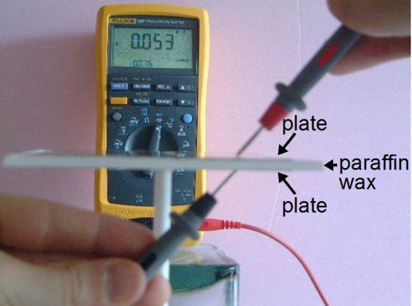
Every now and then you need to make your own capacitor. That includes choosing a dielectric for it, the insulating material that goes between the plates. One dielectric material that I use a lot is paraffin wax which can be found in art stores and is normally used for making candles. Another is resin, the easiest to find being automotive resin used for automotive body repairs.
The problem is that you sometimes need to do the calculations for the capacitor dimensions ahead of time, rather than just throwing something together. And that means you need to know the dielectric constant of the dielectric material. That’s something that the manufacturer of the paraffin wax that makes it for art stores won’t know, nor will the manufacturers of automotive body repair resin. The intended customers just don’t care.
It’s therefore left up to you to measure the dielectric constant yourself, and here I’ll talk about the method I use for doing that.
When a consumer electronics device is sold in the US, especially if it has a wireless aspect, it must be tested for compliance with FCC regulations and the test results filed with the FCC (see preparing your product for FCC testing). These documents are then made available online for all to see in the Office of Engineering and Technology (OET) Laboratory Equipment Authorization System (EAS). In fact, it’s this publishing in this and other FCC databases that has led to many leaks about new product releases, some of which we’ve covered, and others we’ve been privileged enough to know about before the filings but whose breaking was forced when the documents were filed, like the Raspberry Pi 3. It turns out that there are a lot of useful things that can be accomplished by poring over FCC filings, and we’ll explore some of them.
At my university, we were all forced to take a class called Engineering 101. Weirdly, we could take it at any point in our careers at the school. So I put it off for more interesting classes until I was forced to take it in one of my final years. It was a mess of a class and never quite seemed to build up to a theme or a message. However, every third class or so they’d dredge up a veritable fossil from their ranks of graduates. These greybeards would sit at the front of the class and tell us about incredible things. It was worth the other two days of nondescript rambling by whichever engineering professor drew the short straw for one of their TAs.
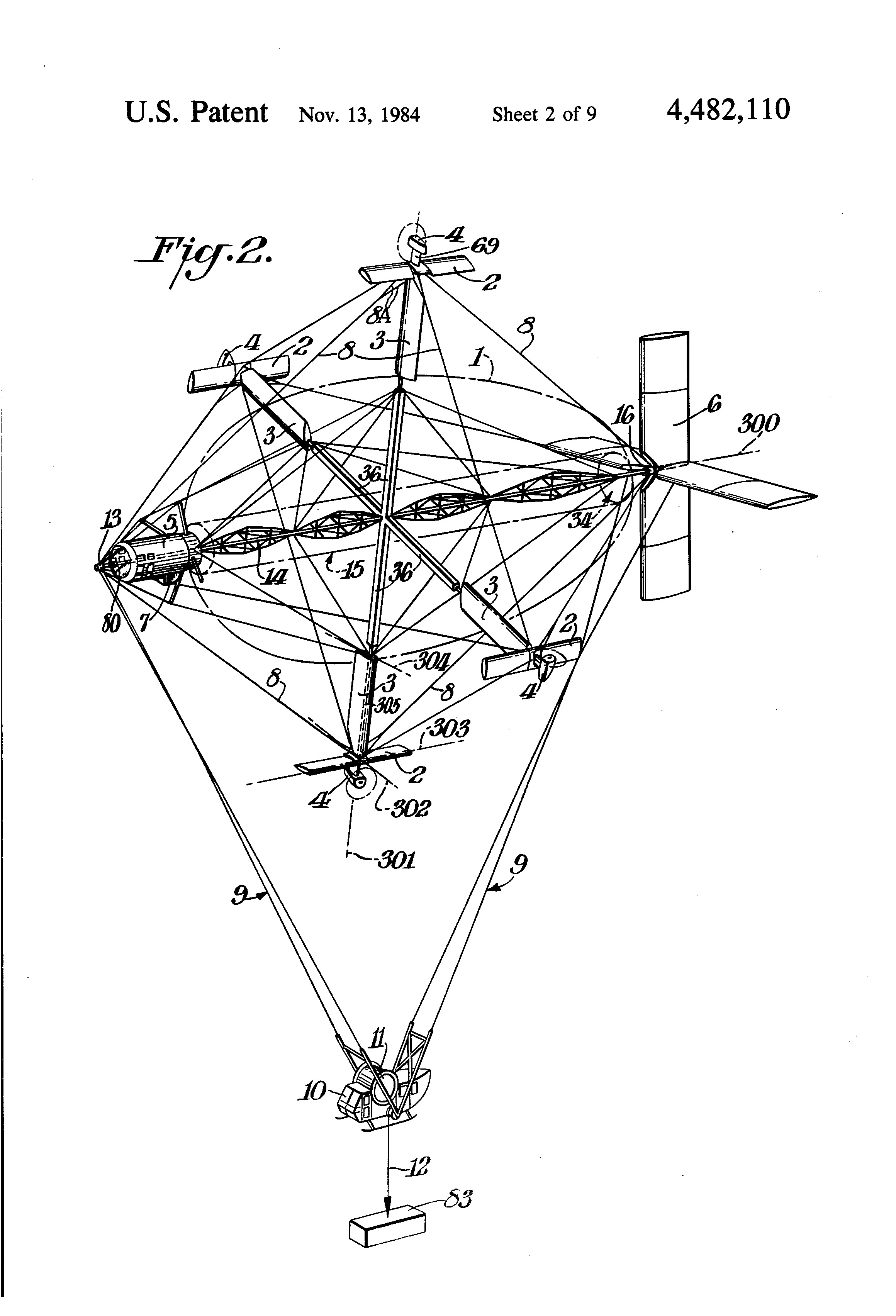
The patent drawing.
One greybeard in particular had a long career in America’s unending string of, “Build cool stuff to help us make bad guys more deader,” projects. He worked on stealth boats, airplanes with wings that flex, and all sorts of incredibly cool stuff. I forgot about the details of those, but the one that stuck with me was the Cyclocrane. It had a ton of issues, and as the final verdict from a DARPA higher-up with a military rank was that it, “looked dumb as shit” (or so the greybeard informed us).
A Cyclo-What?
The Cyclocrane was a hybrid airship. Part aerodynamic and part aerostatic, or more simply put, a big balloon with an airplane glued on. Airships are great because they have a constant static lift, in nearly all cases this is buoyancy from a gas that is lighter than air. The ship doesn’t “weigh” anything, so the only energy that needs to be expended is the energy needed to move it through the air to wherever it needs to go. Airplanes are also great, but need to spend fuel to lift themselves off the ground as well as point in the right direction. Helicopters are cool because they make so much noise that the earth can’t stand to be near them, providing lift. Now, there’s a huge list of pros and cons for each and there’s certainly a reason we use airplanes and not dirigibles for most tasks. The Cyclocrane was designed to fit an interesting use case somewhere in the middle.
In the logging industry they often use helicopters to lift machinery in and out of remote areas. However, lifting two tons with a helicopter is not the most efficient way to go about it. Airplanes are way more efficient but there’s an obvious problem with that. They only reach their peak efficiency at the speed and direction for which their various aerodynamic surfaces have been tuned. Also worth noting that they’re fairly bad at hovering. It’s really hard to lift a basket of chainsaws out of the woods safely when the vehicle doing it is moving at 120mph.
The cyclocrane wanted all the efficiency of a dirigible with the maneuverability of a helicopter. It wanted to be able to use the effective lifting design of an airplane wing too. It wanted to have and eat three cakes. It nearly did.
A Spinning Balloon with Wings
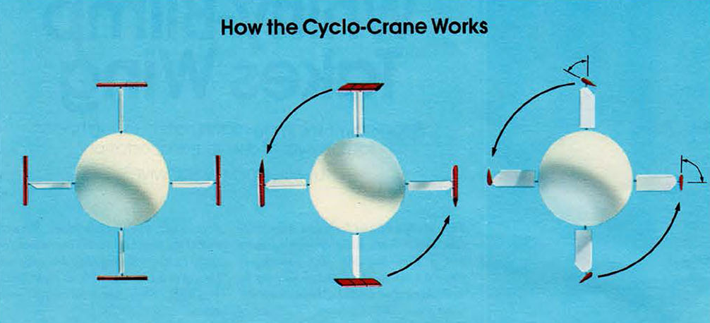
Four wings stick out of a rotating balloon. The balloon provides half of the aerostatic lift needed to hold the plane and the cargo up in the air. The weight is tied to the static ends of the balloon and hang via cables below the construction. The clever part is the four equidistant wings sticking out at right angles from the center of the ship. At the tip of each wing is a construction made up of a propellor and a second wing. Using this array of aerofoils and engines it was possible for the cyclocrane to spin its core at 13 revolutions per minute. This produced an airspeed of 60 mph for the wings. Which resulted in a ton of lift when the wings were angled back and forth in a cyclical pattern. All the while, the ship remaining perfectly stationary.
Now the ship had lots of problems. It was too heavy. It needed bigger engines. It was slow. It looked goofy. It didn’t like strong winds. The biggest problem was a lack of funding. It’s possible that the cyclocrane could have changed a few industries if its designers had been able to keep testing it. In the end it had a mere seven hours of flying time logged with its only commercial contract before the money was gone.
However! There may be some opportunity for hackers here. If you want to make the quadcopter nerds feel a slight sting of jealousy, a cyclocrane is the project for you. A heavy lift robot that’s potentially more efficient than a balloon with fans on it is pretty neat. There’s a bit of reverse engineering to be done before a true performance statement can be made. If nothing else. It’s just a cool piece of aerospace history that reminds us of the comforting fact that we haven’t even come close to inventing it all yet.
If you’d like to learn more there’s a ton of information and pictures on one of the engineer’s website. Naturally wikipedia has a bit to say. There’s also decent documentary on youtube, viewable below.
A few weeks back, we got a taste for two-stage tentacle mechanisms. It’s a look at how to make a seemily complicated mechanism a lot less mysterious. This week, we’ll take a close look at one (of many) methods for puppeteering these beasts by hand. Best of all, it’s a method you can assemble at home!
Without a control scheme, our homebrew tentacle can only “squirm around” about as much as an overcooked noodle. It’s pretty useless without some sort of control mechanism to keep all the cables in check at proper tension. Since the tentacle’s motion is driven by nothing more than four cable pairs, it’s not too difficult to start imagining a few hobby servos and pulleys doing the job. To get us started, though, I’ve opted for hand controllers just like the puppeteers of the film industry.
Enter Manual Control
Hand controllers? Of all the possibilities offered by electronics, why select such an electronics-devoid caveman approach? Fear not. Hand controllers offer us a unique set of opportunities that aren’t easy to achieve with most alternatives.
A few weeks ago I asked the Hackaday community for some help and advice in buying a new budget oscilloscope. Thank you very much to those of you who responded both here online and in person among my friends closer to home. I followed the overwhelming trend in the advice I received, and bought myself a Rigol DS1054z, an instrument with which I am very happy. It’s a nominally a 50 MHz scope, but there’s a software hack that can bring it up to 100 MHz. How fast can it go?
My trusty Cossor, its 2 MHz bandwidth as yet unverified.
This question became a mini scope-shootout after a conversation with my Hackaday colleague [Elliot] about measuring oscilloscope bandwidth, and then my fellow Oxford Hackspace members producing more than one scope for comparison. You know who you are, thank you. I found myself with ready access to several roughly equivalent models and one very high-end one in specification terms representing different strata of test equipment manufacture, and with the means to examine their performance.