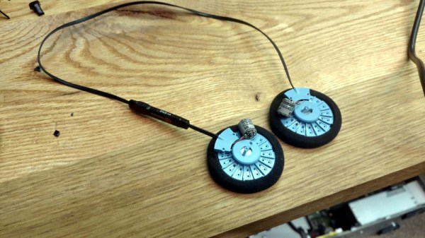
Koss Porta Pro headphones are something of a rarity in the world of audio gear: they’re widely regarded as sounding great, but don’t cost an exorbitant amount of money. Since the line was introduced in 1984, they’ve been the go-to headphones for those who don’t subscribe to the idea that you should have to take out a loan from the bank just to enjoy your music.
 [Jake Bickhard] is a confirmed Porta Pro disciple, owning enough pairs of them that he’s cagey about confirming how many are actually kicking around his home. The only thing he doesn’t like about them is the fact that they’re wired. As it happens, Koss just recently came out with a Bluetooth version of the venerable headphones. But he thought he could do just as well combining a pair of his with a water damaged pair of Bluetooth earbuds he had lying around.
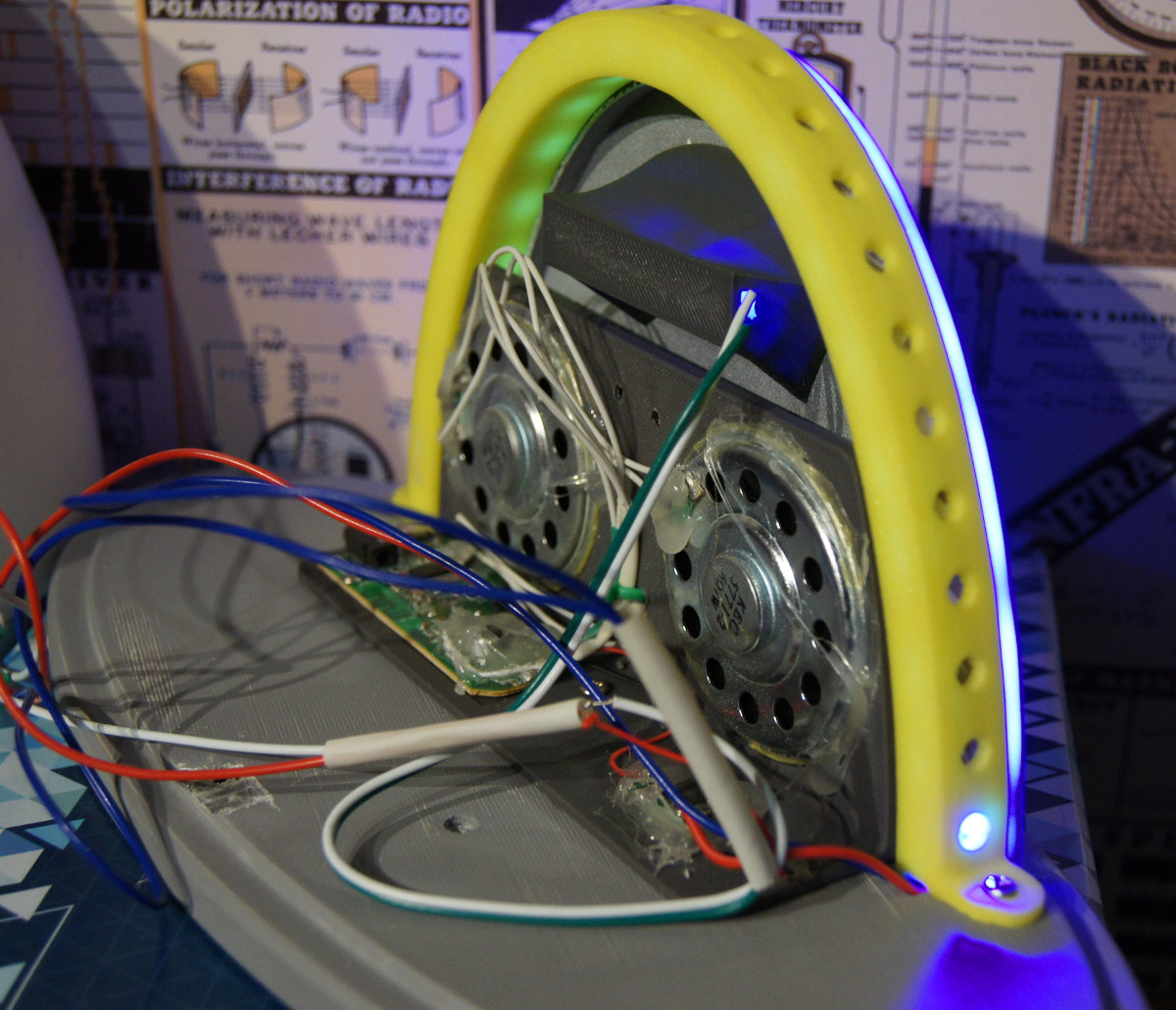
The Porta Pros are easy to take apart, and removing the old wire was no problem. He then cut the “buds” on the Bluetooth earbuds he had, with the intention of just striping the wires and soldering it up to the pads on the Porta speakers. But things didn’t quite go as expected.
What [Jake] hadn’t realized was that the battery for the Bluetooth earbuds wasn’t in the main housing, the power comes from a tiny battery inside each bud. That meant he needed to keep the batteries connected even though the Porta Pro obviously doesn’t have a spot to mount them. In the future he says he’ll address the issue properly, but for now the two batteries hang from the headphones: making it look like he’s wearing the world’s ugliest earrings. But at least he’s happy with the performance of the finished modification, saying they’re even louder now than when they were when wired.
This is a perfect project if you’re cursed with a mobile device that had enough “courage” to take the headphone jack away from you. Though you might first want to study the fine art of soldering headphone wires.