Looks like another shot has been fired in the simmering Coil Gun Control War. This time, [Great Scott] is taken to the discrete woodshed with a simplified and improved control circuit using a single CMOS chip and a few transistors. Where will it end? Won’t somebody think of the children?
The latest salvo is in response to [GreatScott]’s attempt to control a DIY coil gun with discrete logic, which in turn was a response to comments that he took the easy way out and used an Arduino in the original build. [Great Scott]’s second build was intended to justify the original design choice, and seemed to do a good job of explaining how much easier and better the build was with a microcontroller. Case closed, right?
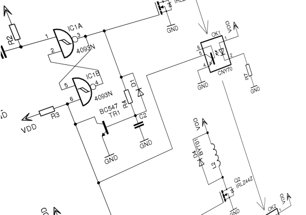
Nope. Embedded designer [fede.tft] wasn’t sure the design was even close to optimized, so he got to work — on his vacation, no less!’ He trimmed the component count down to a single CMOS chip (a quad Schmitt trigger NAND), a couple of switching transistors, the MOSFETs that drive the coils, and a few passives. The NANDs are set up as flip-flops that are triggered and reset by the projectile sensors, which are implemented as hardwired AND gates. The total component count is actually less than the support components on the original Arduino build, and [fede.tft] goes so far as to offer ideas for an alternative that does away with the switching transistors.
Even though [fede.tft] admits that [GreatScott] has him beat since he actually built both his circuits, hats off to him for showing us what can likely be accomplished with just a few components. We’d like to see someone implement this design, and see just how simple it can get.
Summer is the season for family road trips here in the US, and my family took to the open road in a big way this year. We pulled off a cross-country relocation, from Connecticut to Idaho. Five days on the road means a lot of pit stops, and we got to see a lot of truck stops and consequently, a lot of long-haul truckers. I got to thinking about their unique lifestyle and tried to imagine myself doing that job. I wondered what I’d do hour after long hour, alone in the cab of my truck. I figured that I’d probably just end up listening to a lot of audio books, but then I realized that there’s a perfect hobby for the road — ham radio. So I decided to see how ham radio is used by truckers, and mull over how a truck driver version of me might practice The World’s Best Hobby.
I bet the hand saw really changed some things. One day you’re hacking away at a log with an ax. It’s sweaty, awful work, and the results are never what you’d expect. The next day the clever new apprentice down at the blacksmith’s shop is demoing his beta of his new Saw invention and looking for testers, investors, and a girlfriend. From that day onward the work is never the same again. It’s not an incremental change, it’s a change. Pure and simple.
This is one of those moments. The world of tools is seeing a new change, and I think this is the first of many tools that will change the way we build.
Like most things that are a big change, the components to build them have been around for a while. In fact, most of the time, the actual object in question has existed in some form or another for years. Like a crack in a dam, eventually someone comes up with the variation on the idea that is just right. That actually does what everything else has been promising to do. It’s not new, but it’s the difference between crude and gasoline.
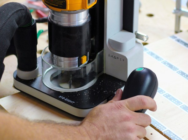
My poetic rasping aside, the Shaper Origin is the future of making things. It’s tempting to boil it down and say that it’s a CNC machine, or a router. It’s just, more than that. It makes us more. Suddenly complex cuts on any flat surface are easy. Really easy. There’s no endless hours with the bandsaw and sander. There’s no need for a 25,000 dollar gantry router to take up half a garage. No need for layout tools. No need to stress about alignment. There’s not even a real need to jump between the tool and a computer. It can be both the design tool and the production tool. It’s like a magic pencil that summons whatever it draws. But even I had to see it to believe it.
“I wasted a weekend learning why elemental bismuth is not commonly used for metal parts.“
It’s a fair assessment of his time spent growing unspectacular bismuth crystals, casting a bismuth cylinder that cracked, and machining bismuth only to be left with a very rough finish. But even though he admits the exercise was unsuccessful, he does provide us with a fascinating look at the physical properties of the element.
This is what [David] wanted to make. Alchemist-hp + Richard Bartz with focus stack. (Own work) [CC BY-SA 3.0], via Wikimedia Commons
Bismuth is one of those elements you pass by in your school chemistry lessons, it has applications in machining alloys and as a lead replacement but most of us have never knowingly encountered it in the real world. It’s one of the heavy metals, below antimony and to the right of lead on the Periodic Table. Curious schoolchildren may have heard that like water it expands on solidifying or that it is diamagnetic, and most of us have probably seen spectacular pictures of its crystals coated in colourful iridescent oxides.
It was a Hackaday story about these crystals that attracted [David] to the metal. It has a low enough melting point – 271.5 °C – that it can be liquified on a domestic stove, so mindful of his marital harmony should he destroy any kitchen appliances he bought a cheap electric ring from Amazon to go with his bismuth ingot. and set to work.
His first discovery was that cheap electric rings outdoors aren’t very effective metallurgy furnaces. Relocating to the kitchen and risking spousal wrath, he did eventually melt his bismuth and pick off the top layer once it had resolidified, to reveal some crystals.
These are the bismuth crystals he made.
Unfortunately for him, instead of spectacular colors and huge crystals, the sight that greeted him was one of little brilliance. Small grey crystals with no iridescence. It seems the beautiful samples are made by a very slow cooling of the liquid bismuth, followed by a quick pouring off of the remaining molten metal. Future efforts, he assures us, will involve sand-insulated molds and careful temperature monitoring.
Undeterred, he continued with his stock of bismuth and embarked on the creation of a cylinder. Early efforts with a clay mold resulted in cracked cylinders, so in desperation he cast the entirety of the metal in an aluminium baking tray and cut the resulting ingot to a rough piece of stock for turning.
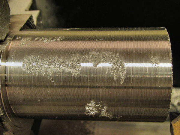
Poor finish on machined bismuth.
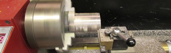
With the bismuth in the lathe, he then came face to face with what he alluded to in his conclusion above, why machined bismuth parts aren’t something you’ll encounter. His cylinder came out with significantly rough patches on the surface, because bismuth is both crystalline and brittle. He suggests improvements could be made if the metal could be solidified with fewer crystals, but it’s obvious that elemental bismuth on its own is not a winner in the turning stakes.
We suggest you take a look at [David]’s write-up. It may be presented as a Fail of The Week here, but in fact it’s more of a succession of experiments that didn’t work than an unmitigated disaster. The result is an interesting and well-documented read that we’re sure most Hackaday readers will gain something from.
Fail of the Week is a Hackaday column which celebrates failure as a learning tool. Help keep the fun rolling by writing about your own failures and sending us a link to the story -- or sending in links to fail write ups you find in your Internet travels.
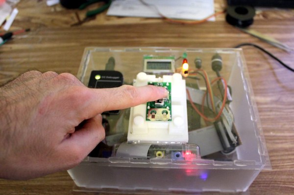
In our final installment of Tools of the Trade (with respect to circuit board assembly), we’ll look at how the circuit board is tested and programmed. At this point in the process, the board has been fully assembled with both through hole and surface mount components, and it needs to be verified before shipping or putting it inside an enclosure. We may have already handled some of the verification step in an earlier episode on inspection of the board, but this step is testing the final PCB. Depending on scale, budget, and complexity, there are all kinds of ways to skin this cat.
Imagine this: you come home after a day at work. As you open the door, your nose is the first alert that something is very, very wrong. Instead of the usual house smell, your nose is assaulted with the distinctive aroma that means your dog had an accident. The smell is stronger though — as if Fido brought over a few friends and they all had a party. Flipping the lights on, the true horror is revealed to you. This was a team effort, but only one dog was involved.
At some point after the dog’s deed, Roomba, your robot vacuum, took off on its scheduled daily run around the house. The plucky little robot performed its assigned duties until it found the mess. The cleaning robot then became an agent of destruction, smearing a foul smelling mess throughout the space it was assigned to clean. Technology sometimes has unintended consequences. This time, your technology has turned against you.
This scene isn’t a work of fiction. For a select few families, it has become an all too odoriferous reality just begging for a clever fix.
You would think that there’s nothing to know about RGB LEDs: just buy a (strip of) WS2812s with integrated 24-bit RGB drivers and start shuffling in your data. If you just want to make some shinies, and you don’t care about any sort of accurate color reproduction or consistent brightness, you’re all set.
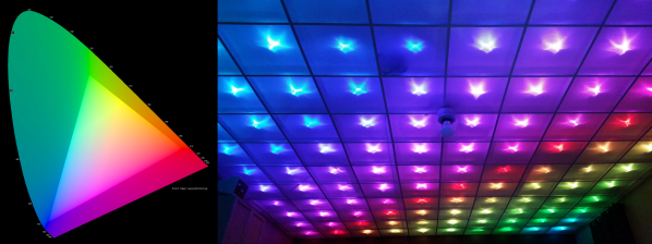
But if you want to display video, encode data in colors, or just make some pretty art, you might want to think a little bit harder about those RGB values that you’re pushing down the wires. Any LED responds (almost) linearly to pulse-width modulation (PWM), putting out twice as much light when it’s on for twice as long, but the human eye is dramatically nonlinear. You might already know this from the one-LED case, but are you doing it right when you combine red, green, and blue?
It turns out that even getting a color-fade “right” is very tricky. Surprisingly, there’s been new science done on color perception in the last twenty years, even though both eyes and colors have been around approximately forever. In this shorty, I’ll work through just enough to get things 95% right: making yellows, magentas, and cyans about as bright as reds, greens, and blues. In the end, I’ll provide pointers to getting the last 5% right if you really want to geek out. If you’re ready to take your RGB blinkies to the next level, read on!


![This is what [David] wanted to make. Alchemist-hp + Richard Bartz with focus stack. (Own work) [CC BY-SA 3.0], via Wikimedia Commons](https://hackaday.com/wp-content/uploads/2016/08/bi-crystal.jpg)

 Fail of the Week is a Hackaday column which celebrates failure as a learning tool. Help keep the fun rolling by writing about your own failures and