
We all have a weakness for a good flamethrower project, but sometimes they can look a little hairy, even if losing hairs to them seems to be the order of the day. [Hyper_Ion] has a ‘thrower that might satisfy the need for fire among the cautious though, because he’s created a remote control flamethrower.
Fuel for the flames is provided from a butane canister held within a 3D-printed frame, and is delivered via a piece of copper tube to a welding nozzle. A plunger beneath the can is connected to a rack-and-pinion driven by a servo, connected to a straightforward radio control receiver. The position of the can is adjusted until there is just enough gas to sustain a pilot flame at the nozzle, and a command to the servo releases a burst of gas that results in a satisfying puff of fire.
This is more of a static stage effect than the wearable flamethrowers or flamethrower guitar projects we’ve seen in the past, but it is no less a neat project. And unlike many other flamethrowers, it’s simple to build. We have to deliver the usual exhortation though: take care with your fire, we’d prefer not to be writing either obituaries of Fail Of The Week posts about smoking ruins.


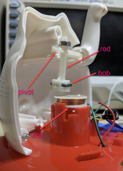 Perhaps unsurprisingly given the prevalence and cost of these devices, the answer is quite simple. The key interaction is between a permanent magnet mounted to the end of the waving arm/pendulum and a many-turn wire coil attached to the body. As the magnet swings over the coil, its movement induces a voltage. A small blob of analog circuitry reacts by running current through the coil. The end effect is that it “senses” the magnet passing by and gives it a little push to keep things moving. As long as there is light the circuit can keep pushing and the pendulum swings forever. If it happens to stop a jolt from the coil starts the pendulum swinging and the rest of the circuit takes over again. [Josh] points to a similar circuit with a


