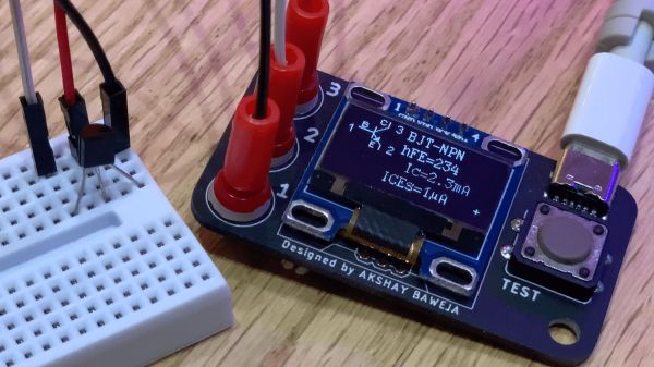
The ideal component tester is like a tricorder for electronics — it can measure whatever it is that you need it to, all the time. Maybe you have a few devices like an ohmmeter and maybe a transistor socket on our multimeter. But what do you do when you need to see if that thyristor is faulty? [Akshay Baweja] wants an everything-tester at the ready, so he’s building a comprehensive device that fits in a pocket. It will identify the type and size of: Continue reading “Check Your Pockets For Components”→
Internet-connected sex toys are a great way to surprise your partner from work (even the home office) or for spicing up long-distance relationships. For some extra excitement, they also add that thrill of potentially having all your very sensitive private data exposed to the public — but hey, it’s not our place to kink-shame. However, their vulnerability issues are indeed common enough to make them regular guests in security conferences, so what better way to fight fire with fire than simply inviting the whole of Twitter in on your ride? Well, [Space Buck] built just the right device for that: the Double-Oh Battery, an open source LiPo-cell-powered ESP32 board in AA battery form factor as drop-in replacement to control a device’s supply voltage via WiFi.
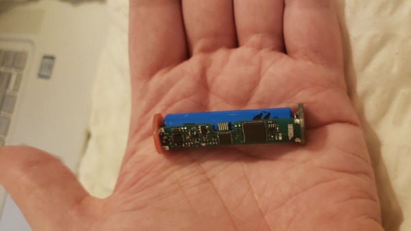
Double-Oh Battery with all the components involved
In their simplest and cheapest form, vibrating toys are nothing more than a battery-powered motor with an on-off switch, and even the more sophisticated ones with different intensity levels and patterns are usually limited to the same ten or so varieties that may eventually leave something to be desired. To improve on that without actually taking the devices apart, [Space Buck] initially built the Slot-in Manipulator of Output Levels, a tiny board that squeezed directly onto the battery to have a pre-programmed pattern enabling and disabling the supply voltage — or have it turned into an alarm clock. But understandably, re-programming patterns can get annoying in the long run, so adding WiFi and a web server seemed the logical next step. Of course, more functionality requires more space, so to keep the AA battery form factor, the Double-Oh Battery’s PCB piggybacks now on a smaller 10440 LiPo cell.
But then, where’s the point of having a WiFi-enabled vibrator with a web server — that also happens to serve a guestbook — if you don’t open it up to the internet? So in some daring experiments, [Space Buck] showcased the project’s potential by hooking it up to his Twitter account and have the announcement tweet’s likes and retweets take over the control, adding a welcoming element of surprise, no doubt. Taking this further towards Instagram for example might be a nice vanity reward-system improvement as well, or otherwise make a great gift to send a message to all those attention-seeking people in your circle.
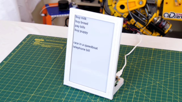
Are you still writing notes on paper and sticking them to the fridge like it’s the ’80s? Well, if you are, and you read this site, you’d probably like to upgrade to something a bit more 21st century. And, thanks to robot maker [James Bruton], you can leave your old, last century, message taking behind as he has a tutorial up showing you how to build an internet connected e-paper message display board. And, if you have a Raspberry Pi, an e-paper display and adapters just lying around doing nothing, then this project will cost you less than the buck that paper and a magnet will cost you.
Sarcasm aside, this is a pretty nice project. As mentioned, the base of this is a Raspberry Pi – [James] uses a Pi 4, but you could get away with an older, lower powered model as well. This powers the cheap(-ish) e-paper display he found online, which comes with the necessary adapters for the Pi, as well as a python library to write to the display. [James] uses a Google Sheet as the cloud storage for the message board, and there is some python code to access the cells in the Sheet and print them on the display if anything has changed. A cron job runs the script every 5 minutes to catch changes in the messages.
As with most of the projects that [James] does, he gives a good overview in the video and goes over the process of finding the hardware and writing and updating the script. He’s put the script and details as well as the CAD file for the frame he created for the project up on GitHub. [James] has been featured several times on the site before, check out some of his projects.
Modern-day hard disk drives (HDDs) hold the interesting juxtaposition of being simultaneously the pinnacle of mass-produced, high-precision mechanical engineering, as well as the most scorned storage technology. Despite being called derogatory names such as ‘spinning rust’, most of these drives manage a lifetime of spinning ultra-smooth magnetic storage platters only nanometers removed from the recording and reading heads whose read arms are twitching around using actuators that manage to position the head precisely above the correct microscopic magnetic trace within milliseconds.
Despite decade after decade of more and more of these magnetic traces being crammed on a single square millimeter of these platters, and the simple read and write heads being replaced every few years by more and more complicated ones, hard drive reliability has gone up. The second quarter report from storage company Backblaze on their HDDs shows that the annual failure rate has gone significantly down compared to last year.
The question is whether this means that HDDs stand to become only more reliable over time, and how upcoming technologies like MAMR and HAMR may affect these metrics over the coming decades.
FPGAs are somewhat the IPv6 of integrated circuits — they’ve been around longer than you might think, they let you do awesome things that people are intrigued by initially, but they’ve never really broke out of their niches until rather recently. There’s still a bit of a myth and mystery surrounding them, and as with any technology that has grown vastly in complexity over the years, it’s sometimes best to go back to its very beginning in order to understand it. Well, who’d be better at taking an extra close look at a chip than [Ken Shirriff], so in his latest endeavor, he reverse engineered the very first FPGA known to the world: the Xilinx XC2064.
If you ever wished for a breadboard-friendly FPGA, the XC2064 can scratch that itch, although with its modest 64 configurable logic blocks, there isn’t all that much else it can do — certainly not compared to even the smallest and cheapest of its modern successors. And that’s the beauty of this chip as a reverse engineering target, there’s nothing else than the core essence of an FPGA. After introducing the general concepts of FPGAs, [Ken] (who isn’t known to be too shy to decap a chip in order to look inside) continued in known manner with die pictures in order to map the internal components’ schematics to the actual silicon and to make sense of it all. His ultimate goal: to fully understand and dissect the XC2064’s bitstream.
Over the last couple of years, we’ve seen a wave of impressive rugged mobile computing devices based on the ubiquitous Raspberry Pi. Sometimes they involve repurposing an existing heavy duty enclosure, and in others the Pi takes up residence in a 3D printed case which may or may not be as strong as it appears. In either event, they usually don’t lend themselves to duplication because of the time and expense involved in tracking down or printing all the parts required.
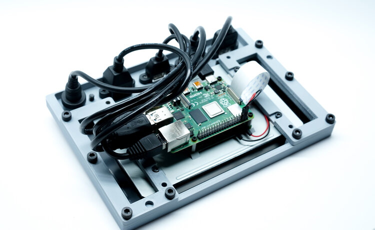
But the Raspberry Pi Quick Kit by [Jay Doscher] may change that. It represents what must surely be the simplest and fastest route to a building a rugged mobile ARM computer for your hacking adventures. Beyond the Pelican 1150 case that serves as the outer enclosure, you only need three printed parts and a handful of fasteners to complete the build. Of course you’ll need a Raspberry Pi and the official touch screen as well, but that’s sort of a given.
Electronics mounted to the 3D printed frame.
All of the electronics mount onto the three piece 3D printed frame, which is then press-fit into the opening of the Pelican case. Since you don’t need to pop any holes through the case itself, the assembled unit remains water and air tight. While [Jay] has recently shown off a very impressive 3D printed Pi enclosure, there’s really no beating a legitimate heavy duty storage case if you’re trying to protect the hardware.
When you want to use the Pi, just open the case and plug your power and accessories into the panel mount connectors under the display. There’s no integrated battery or keyboard on this build, but considering how small it is, that shouldn’t really come as a surprise.
[Jay] is targeting the Pi 4 for the Quick Kit, so that means WiFi and Bluetooth will come standard without the need for any external hardware. It looks like there might just be enough room to include an RTL-SDR receiver inside the case as well, but you’ll need to do a little redesigning of the 3D printed parts. If you do modify this design to pack in a few new tricks, we’d love to hear about it.
Pedaling in place isn’t the most exciting pastime, so it’s no surprise that modern technology is being used to make the in-home biking experience a bit more interactive. With a stand on the rear wheel providing resistance, and a movable steering plate under the front to read the handlebar angle, you can now use your standard bike as the “controller” in a virtual environment provided by software such as Zwift.
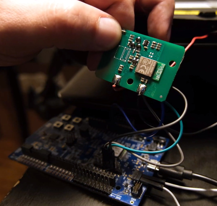
Paving the way towards a DIY Sterzo clone
[Keith Wakeham] wanted to take a closer look at how Zwift communicated with his Sterzo steering device, and it turned into a pretty epic bout of exploration and reverse engineering. As the video after the break shows, he didn’t just go from sniffing the device’s proprietary Bluetooth Low Energy (BLE) communications protocol to figuring out how to emulate it in software so you could roll your own Zwift peripheral. He also tore the device apart, pulled the firmware from its microcontroller, and postulated how you could build your own low-cost clone device that would work with the existing software.
Even if you have absolutely zero interest in virtual biking, the video [Keith] has put together for this project is really a must watch. Have you ever wanted to sniff and reverse engineer BLE communications? Looking for a real-world example of pulling the firmware off of a consumer device? Maybe in the market for some tips on how to identify unknown ICs on a board? All of that, and quite a bit more, is covered in this nearly hour long hacking tour de force.