There’s kind of a special joy in making instruments, no matter how simple or complex they are. Even if it’s a straight-up noisemaker, that’s noise you can be proud of. And besides, noise plus rhythm equals music.
Whenever you’re ready to have some next-level fun, try making controllers for your DIY instruments. Synthesizers of all stripes are often controlled with various types of potentiometers. While it would definitely be an interesting exercise to make your own standard twist-style potentiometer, [lonesoulsurfer] shows that making a ribbon controller is relatively easy.
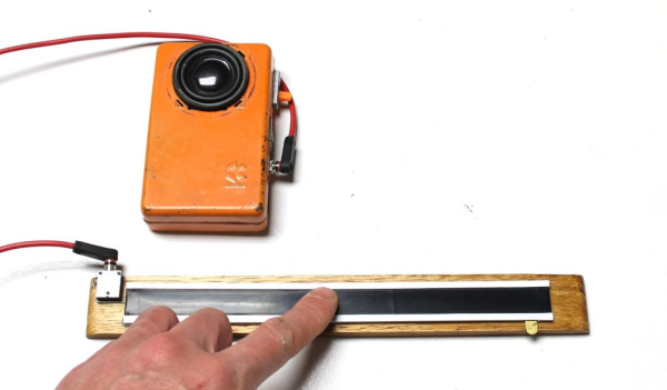
 A ribbon controller is essentially a deconstructed potentiometer that uses your finger to actuate the wiper. Here the wiper is made from Velostat, a fun, low-cost conductive material that’s also pressure-sensitive. The rest of the ribbon controller is a sandwich of thin copper plates and non-conductive plastic mounted on a wood base.
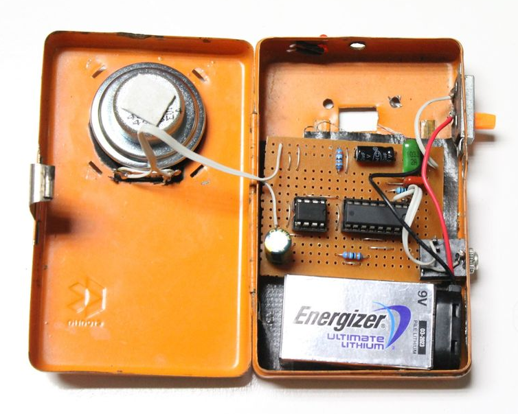
But what’s a fun controller without a fun instrument to control? As a special bonus, [lonesoulsurfer] made a little square wave-squirting synth based on the 4046 hex inverter and included the schematic for it. Slide your finger past the break to check ’em both out.
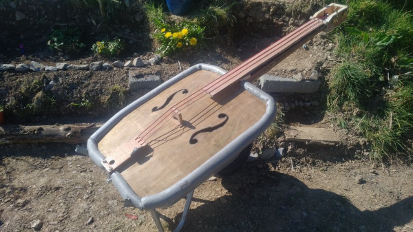
Depending on what you have lying around, it may be easier to make analog instruments like this rubber band boinger or its country cousin, the wheelbarrow bass.