When I began programming microcontrollers in 2003, I had picked up the Atmel STK-500 and learned assembler for their ATtiny and ATmega lines. At the time I thought it was great – the emulator and development boards were good, and I could add a microcontroller permanently to a project for a dollar. Then the ESP8266 came out.
I was pretty blown away by its features, switched platforms, except for timing-sensitive applications, and it’s been my chip of choice for a few years. A short while ago, a friend gave me an ESP32, the much faster, dual core version of the ESP8266. As I rarely used much of the computing power on the ESP8266, none of the features looked like game changers, and it remained a ‘desk ornament’ for a while.
About seven weeks ago, support for the libSodium Elliptic Curve Cryptography library was added. Cryptography is not the strongest feature of IoT devices, and some of the methods I’ve used on the ESP8266 were less than ideal. Being able to more easily perform public-private key encryption would be enough for me to consider switching hardware for some projects.
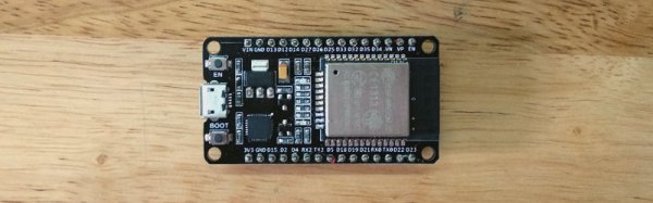
However, my preferred automated build tool for NodeMCU wasn’t available on the ESP32 yet. Compiling the firmware was required – this turned out to be a surprisingly user-friendly experience, so I thought I’d share it with you. If I had known it would be so quick, this chip wouldn’t have sat on my desk unused quite so long! Continue reading “Compiling NodeMCU For The ESP32 With Support For Public-Private Key Encryption”
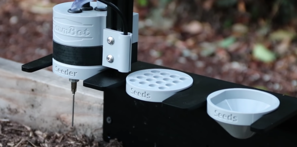
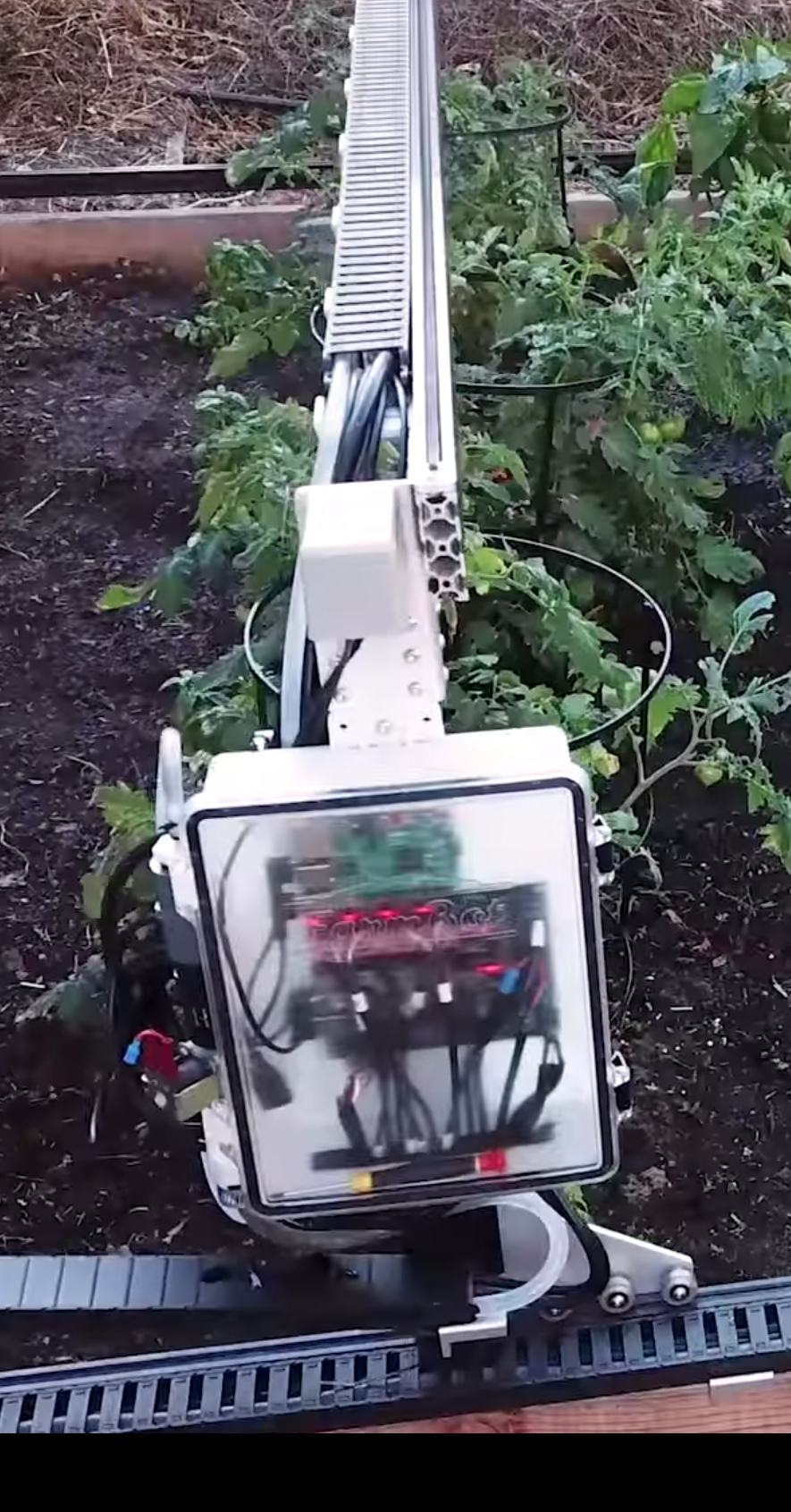 Years ago the first and second Hackaday Prizes captured an entrant named FarmBot whose goal was to build open source robotic farming equipment to make it easier for anyone to grow their own food. A few successful Kickstarters and years later they’ve been shipped multiple versions of the Genesis and Genesis XL robotic farming system and have a sustainable business! And now they’ve decided to open source their
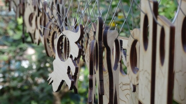
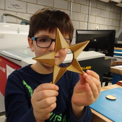 It all began when the kids were taken to a local fab lab at the École Polytechnique and made some laser-cut napkin holders from plywood for personal use. Later, they decided to design, manufacture, and sell them at the Ottawa Maker Faire. Money for the plywood came from piggy banks, 23 different designs made the cut, and a total of 103 rings were made. A display board and signs made from reclaimed materials rounded out the whole set.