If necessity is the mother of invention, then laziness is probably its father. Or at least a close uncle. Who hasn’t thought, “There has to be a better way to do this, one that doesn’t involve me burning precious calories”?
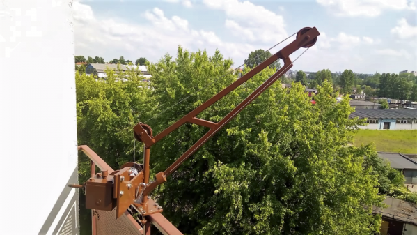
Motivational laziness seems to increase with potential energy, as anyone who needs to haul groceries up four flights of stairs will tell you. This appears to be where this balcony-mounted drill-powered crane came from. Starting with a surplus right-angle gearbox and drum, [geniusz K] fabricated the rest of the crane from steel plate and tubing. We like the quality of fabrication and the tip on making slip couplings from bits of square tubing. The finished product got a nice coat of brown paint to match the balcony railing; keeping the neighbors happy is always important. He tested the crane with a 20-kg weight before installing it on the balcony and put it to work hauling groceries up three stories. Check out the build and the test in the video below.
While it won’t set any speed records, at least the drill is doing the work. But what if you’re impatient as well as lazy? Aside from being two-thirds of the way to programming greatness, you may have to up the game. A heavy-lift quadcopter, perhaps?
Continue reading “A DIY Balcony Crane Lifts Groceries For The Lazy But Patient”
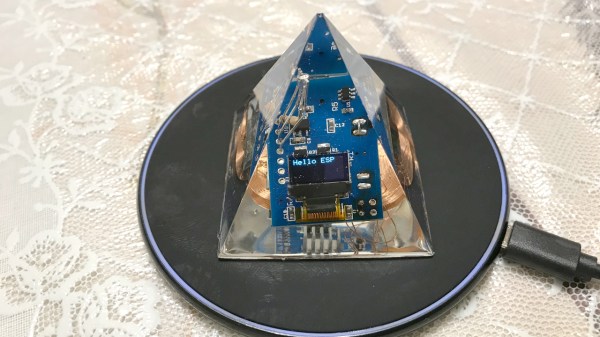
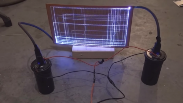
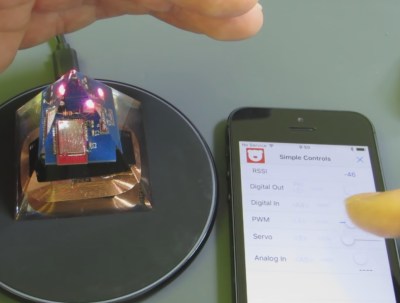 His first works of electronic art were a couple of transistors and some ICs, including an 80386, encased in epoxy. But then he realized that he wanted the electronics to do something interesting. However, once encased in epoxy, how do you keep the electronics powered forever?
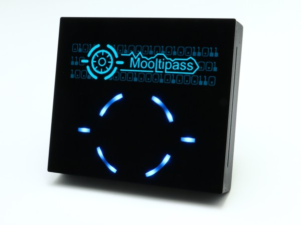
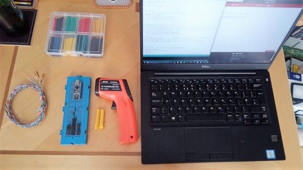
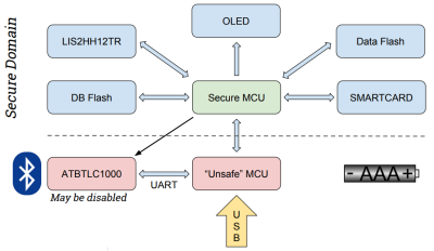 The key to the hardware is the use of a smartcard with proven encryption to store your passwords. Mooltipass is a secure interface between this card and a computer via USB. The new version will be a challenge as it introduces BLE for connectivity with smart phones. To help mitigate security risks, a second microcontroller is added to the existing design to act as a gatekeeper between the secure hardware and the BLE connection.