One of the best things about the Internet — especially the video part — is that you can get exposed to lots of things you might otherwise not be able to see. Take oscilloscopes, for example. If you were lucky, you might have one or two really nice instruments at work and you certainly weren’t going to be allowed to tear them open if they were working well. [The Signal Path], as a case in point, tears down a $30,000 MSO6 8 GHz oscilloscope.
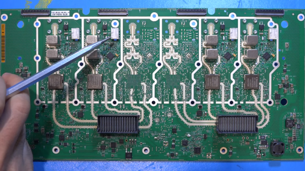
Actually, the base price is not quite $30,000 but by the time you outfit one, you’ll probably break the $30K barrier. Compared to the scopes we usually get to use, these are very different. Sure, the screens are larger and denser, but looking at the circuit boards they look more like some sort of high-end computer than an oscilloscope. Of course, in a way, that’s exactly what it is.