The advantage of the irregularities in the Gregorian calendar combined with the seven-day week is that they provide a constant source of yearly revenue for the paper calendar industry. Long before sustainability became a trending topic, people invented reusable, perpetual calendars, but the non-digital versions of these are sometimes complicated tables that are hard to interpret. [andrei.erdei] created an automated perpetual calendar that is mostly hardware but uses some digital tricks to overcome these problems.
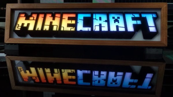
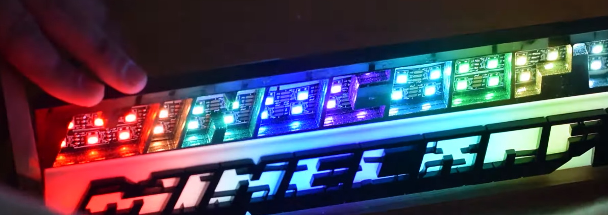
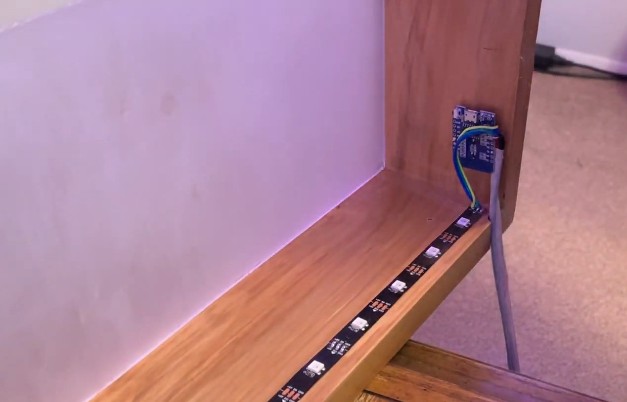
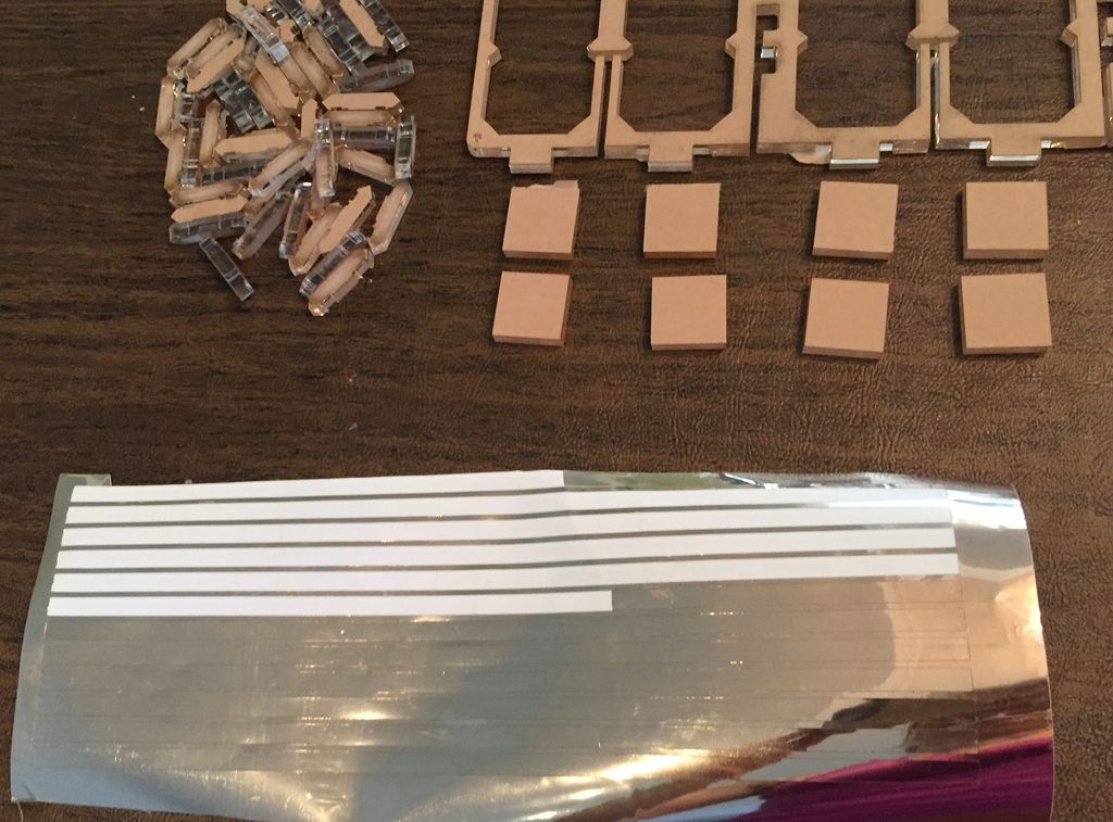
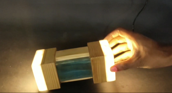
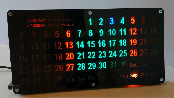
The calendar consists of sandwiched panels of smoked acrylic which are backlit by some strips of WS2812Bs. Although the panels could have been processed with a laser cutter, [andrei.erdei] used a CNC which gave him the possibility to mill some grooves in the back panel to hold the LED strips. The stencil for the numbers was simply printed out on paper and the background made opaque by printing several times over the same piece of paper. The electronics consist of an ESP8266 which takes the date from an NTP server and lights up the corresponding LEDs in different colors for weekdays and weekends.
The classic version of this type of perpetual calendar uses a sliding frame but we have also seen completely different versions based on moving gears.
Video after the break.