Matrix Of Resistors Forms The Hot Hands Behind This Thermochromic Analog Clock

If you’re going to ditch work, you might as well go big. A 1,024-pixel thermochromic analog clock is probably on the high side of what most people would try, but apparently [Daniel Valuch] really didn’t want to go to work that day.

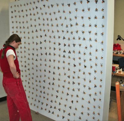
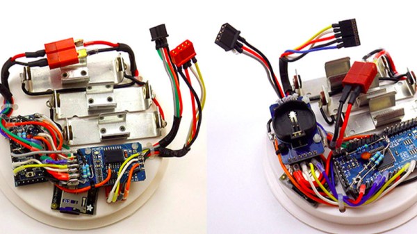
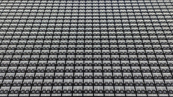
The idea here is simple: heat up a resistor by putting some current through it, lay a bit of thermochromic film over it, and you’ve got one pixel. The next part was not so simple: expanding that single pixel to a 32 by 32 matrix.

To make each pixel square-ish, [Daniel] chose to pair up the 220-ohm SMD resistors for a whopping 2,048 components. Adding to the complexity was the choice to drive them with a 1,024-bit shift register made from discrete 74LVC1G175 flip flops. With the Arduino Nano and all the other support components, that’s over 3,000 devices with the potential to draw 50 amps, were someone to be foolish or unlucky enough to turn on every pixel at once. Luckily, [Daniel] chose to emulate an analog clock here; that led to additional problems, like dealing with cool-down lag in the thermochromic film when animating the hands, which had to be dealt with in software.

We’ve seen other thermochromic displays before, including recently with this temperature and humidity display. This one may not be the highest resolution display out there, but it’s big and bold and slightly dangerous, and that makes it a win in our book.

Go The Extra Mile For Your LED Driver

Addressable RGB LED strips may be all the rage, but that addressability can come at a cost. If instead of colors you expect to show shades of white you may the find less flickery, wider spectrum light from a string of single color LEDs and a nice supply desirable. Of course there are many ways to drive such a strip but this is Hackaday, not Aliexpressaday (though we may partake in the sweet nectar of e-commerce). [Niklas Fauth] must have really had an itch to scratch, because to get the smoothest fades for his single color LED strips, he built an entire software defined dual 50W switched-mode AC power supply from scratch. He calls it his “first advanced AC design” and we are suitably impressed.

Switched-mode power supplies are an extremely common way of converting arbitrary incoming AC or DC voltage into a DC source. A typical project might use a fully integrated solution in the form of a drop-in module or wall wart, or a slightly less integrated controller IC and passives. But [Niklas] went all the way and designed his from scratch. Providing control he has the ubiquitous ESP-32 to drive the control nodes of the supply and giving the added bonus of wireless connectivity (one’s blinkenlights must always be orchestrated). We can’t help but notice the PCBA also exposes RS485 and CAN transceivers which seem to be unused so far, perhaps for a future expansion into wired control?

Continue reading “Go The Extra Mile For Your LED Driver”

The Fart Box, A Synthesizer Not Quite Like Others

[lookmumnocomputer] enjoys creating synthesizers, and early last year he created one called The Fart Box. It is an entirely analog synthesizer with which, according to its creator, it is difficult to make anything that doesn’t sound gassy. It’s not quite like any other synthesizer, and while it is capable of acting like a regular analog synth it is never very far from cranking out farty sounds.

One may think this is just a gimmick, but it can actually be quite musical. There’s a good demonstration at the 7:09 mark in the video of what it can do. Entirely hand-made, it’s definitely a labor of love. There’s a bill of materials and a wiring diagram (of a sort) for anyone who is interested in such details, but it looks like it was a limited run only. [lookmumnocomputer]’s whole video is embedded below, and he demonstrates its ability to act more like a “normal” synthesizer around 8:30.

Continue reading “The Fart Box, A Synthesizer Not Quite Like Others”

Kelly Heaton’s Artwork Blurs The Line Between Traditional And Electronic

Digital electronics are all well and good, but it’s hard to ignore the organic, living qualities of the analog realm. It’s these circuits that Kelly Heaton spends her time with, building artistic creations that meld the fine arts with classic analog hardware to speak to the relationship between electronics and nature. During her talk at the 2019 Hackaday Superconference, Kelly shared the story of her journey toward what she calls Electronic Naturalism, and what the future might bring.

The Pool of Reflection Loop was one of Kelly’s early electronic installation pieces.

Kelly got her start like many in the maker scene. Hers was a journey that began by taking things apart, with the original Furby being a particular inspiration. After understanding the makeup of the device, she began to experiment, leading to the creation of the Reflection Loop sculpture in 2001, with the engineering assistance of Steven Grey. Featuring 400 reprogrammed Furbys, the device was just the beginning of Kelly’s artistic experimentation. With an interest in electronics that mimicked life, Kelly then moved on to the Tickle Me Elmo. Live Pelt (2003) put 64 of the shaking Muppets into a wearable coat, that no doubt became unnerving to wear for extended periods.

Analog electronics parallel living organisms while programmable logic merely simulates life.

Forrest Mims

Wanting to create art with a strong relationship to organic processes, Kelly focused on working with discrete components and analog circuitry. Basic building blocks such as the astable multivibrator became key tools that were used in different combinations to produce the desired effects. Through chaining several oscillators together, along with analog sequencers, circuits could be created that mimicked the sound of crickets in a backyard, or a Carolina wren singing in a tree.

Continue reading “Kelly Heaton’s Artwork Blurs The Line Between Traditional And Electronic”

RTFM: ADCs And DACs

It’s tough to find a project these days that doesn’t use an analog-to-digital converter (ADC) or digital-to-analog converter (DAC) for something. Whether these converters come as built-in peripherals on a microcontroller, or as separate devices connected over SPI, I2C, or parallel buses, all these converters share some common attributes, and knowing how to read the specs on them can save you a lot of headaches when it comes to getting things working properly.

There are some key things to know about these devices, and the first time you try to navigate a datasheet on one, you may find yourself a bit confused. Let’s take a deep dive into the static (DC) properties of these converters — the AC performance is complex enough to warrant its own follow-up article.

Continue reading “RTFM: ADCs And DACs”

[Ben Krasnow] Looks Inside Film Camera Date Stamping

Honestly, we never wondered how those old film cameras used to put the date stamp in the lower right-hand corner of the frame. Luckily, [Ben Krasnow] does not suffer from this deplorable lack of curiosity, and his video teardown of a date-stamping film camera back (embedded below) not only answers the question, but provides a useful lesson in value engineering.

For the likely fair fraction of the audience who has never taken a photo on film before, cheap 35-mm cameras were once a big thing. They were really all one had for family snapshots and the like unless you wanted to invest in single-lens reflex cameras and all the lenses and accessories. They were miles better than earlier cartridge cameras like the 110 or – shudder – Disc film, and the cameras started getting some neat electronic features too. One was the little red-orange date stamp, which from the color we – and [Ben] assumed was some sort of LED pressed up against the film, but it ends up being much cooler than that.

Digging into the back of an old camera, [Ben] found that there’s actually a tiny projector that uses a mirror to fold the optical path between the film and a grain-of-wheat incandescent bulb. An LCD filter sits in the optical path, but because it’s not exactly on the plane of the film, it actually has to project the image onto the film. The incandescent bulb acts as a point source and the mirror makes the optical path long enough that the date stamp image appears sharp on the film. It’s cheap, readily adapted to other cameras, and reliable.

Teardowns like this aren’t fodder for [Ben]’s usual video fare, which tends more toward homemade CT scanners and Apollo-grade electroluminescent displays, but this was informative and interesting, too.

Continue reading “[Ben Krasnow] Looks Inside Film Camera Date Stamping”

High Precision Analog IO With Digital Pins

Reading the temperature of your environment is pretty easy right? A quick search suggests the utterly ubiquitous DHT11, which speaks a well documented protocol and has libraries for every conceivable microcontroller and platform. Plug that into your Arduino and boom, temperature (and humidity!) readings. But the simple solution doesn’t hit every need, sometimes things need to get more esoteric.

The technique summarized by an image from Microchip Appnote AN685

For years we’ve been watching [Edward]’s heroic efforts to build accessible underwater sensing hardware. When we last heard from him he was working on improving the accuracy of his Arduino’s measurements of the humble NTC thermistor. Now the goal is the same but he has an even more surprising plan, throw the ADC out entirely and sample an analog thermistor using digital IO. It’s actually a pretty simple trick based on an intuitive observation, that microcontrollers are better at measuring time than voltage. 

The basic circuit

The circuit has a minimum of four components: a reference resistor, the thermistor, and a small capacitor with discharge resistor. To sense you configure a timer to count, and an edge interrupt to capture the value in the timer when its input toggles. One sensing cycle consists of discharging the cap through the discharge resistor, enabling the timer and interrupt, then charging it through the value to measure. The value captured from the timer will be correlated to how long it took the cap to charge above the logic-high threshold when the interrupt triggers. By comparing the time to charge through the reference against the time to charge through the thermistor you can calculate their relative resistance. And by performing a few calibration cycles at different temperatures ([Edward] suggests at least 10 degrees apart) you can anchor the measurement system to real temperature.

For all the gory details, including tips for how to save every last joule of energy, check out [Edward]’s post and the Microchip appnote AN685 he references. Besides this series [Edward]’s Cave Pearl Project has already yielded an impressive number of Hackday posts. For more great hardware writeups check out a general hardware build for a single sensing node, or the “temperature sensor” [Edward] made with no external parts at all!