[Mark Aren] purchased a pair of Turbomolecular pumps (TMP) sans controllers, and then built an FPGA based BLDC controller for the Turbomolecular pumps. A TMP is similar to a jet turbine, consisting of several stages of alternating moving turbine blades and stationary stator blades, and having turbine rotation speeds ranging from 10,000 rpm to 90,000 rpm. TMP’s cannot exhaust directly to atmosphere, and must be combined with a backing (or roughing) pump to create a lower grade vacuum first. They find use in lots of applications such as electron microscopy, analytical sciences, semiconductors and lamp manufacturing. With the lamp industry rapidly embracing LEDs, many of the traditional lamp making lines are getting decommissioned, and if you are lucky, you can snag a TMP at a low cost – but it still will not be cheap by any means.
The two BOC-Edwards EXT255H Compound Molecular Pumps (PDF), that [Mark] bought did not have their accompanying EXC100E Turbomolecular Pump Controllers (PDF), and given pandemic related restrictions, he decided to build a controller of his own, using components and modules from his parts bin. The pump and controller user manuals offered only sketchy details about the sensored BLDC motor used in the pump. The low phase-to-phase resistance implied low drive voltage, and [Mark] decided to try running it at 24 V to start with. He already had experience using the Mitsubishi PS21245-E IGBT inverter bridge, and even though it was rated for much higher voltages, he knew that it would work just fine at 24 V too.
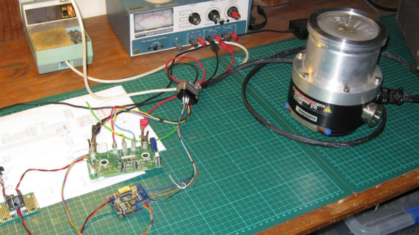
After figuring out a state machine for motor commutation that utilized PWM based adjustable current control, he implemented it on a 128 element FPGA board. Considering how expensive the TMP was, he wisely decided to first try out his driver on a smaller “expendable” BLDC motor. This whole process was non-trivial, since his available IGBT module was untested and undocumented, and required several tweaks before he could run it at the required 12 kHz PWM signals. His test motor was also undocumented, failing to run correctly when first hooked up. Fixing that issue meant having to disassemble the motor to check its internal wiring. Eventually, his efforts paid off, and he was able to safely run the TMP motor to confirm that his design worked.
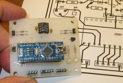 With FPGA code, IGBT wiring and power supply issues sorted, the next step was to add a supervisory micro-controller, using an Arduino Nano. Its functions included interfacing with a touch screen LCD as a user interface, communicating with the FPGA module, and controlling several relays to switch power to the motor power supply, the roughing pump, TMP cooling fan, and a solenoid for the vacuum vent. Spindle current is calculated by measuring voltage drop across shunt resistors on the low side of the IGBT. Motor speed is measured using one of the motor hall sensors, and a thermistor provides motor temperature sensing. [Mark]’s PCB fabrication technique seems a bit different too. Using an Excellon drill file, he drills holes in a piece of plastic using a laser cutter to create a bare board, and then solders copper tracks by hand.
His initial tests at atmospheric pressure (although not recommended unless you monitor pump temperature), resulted in 7300 rpm while consuming about 7 Amps before he had to shut it down. In further tests, after adding a roughing pump to the test setup, he was able to spin the TMP to 20,000 rpm while it consumed 0.6 A. Obviously, the pump is rated to operate at a higher voltage, possibly 48 V based on the values mentioned in the TMP controller manual. The project is still “work in progress” as [Mark] hopes to eventually drive the pump up to its specified 60,000 rpm operating speed. What is not clear is what he eventually intends to do with this piece of exotic machinery. All he mentions is that “he has recently taken an interest in high-vacuum systems and is interested in exploring the high-vacuum world of electron guns.”
Maybe [Mark] can compare notes with the Open Source Turbomolecular Pump Controller that we featured some time back. And if you’d like to be a little bit more adventurous and build you own TMP, we got you covered with this DIY Everyman’s Turbomolecular Pump.


 With FPGA code, IGBT wiring and power supply issues sorted, the next step was to add a supervisory micro-controller, using an Arduino Nano. Its functions included interfacing with a touch screen LCD as a user interface, communicating with the FPGA module, and controlling several relays to switch power to the motor power supply, the roughing pump, TMP cooling fan, and a solenoid for the vacuum vent. Spindle current is calculated by measuring voltage drop across shunt resistors on the low side of the IGBT. Motor speed is measured using one of the motor hall sensors, and a thermistor provides motor temperature sensing. [Mark]’s PCB fabrication technique seems a bit different too. Using an Excellon drill file, he drills holes in a piece of plastic using a laser cutter to create a bare board, and then solders copper tracks by hand.