Build An Everlasting Continuity Tester

When you need a continuity tester at the bench, what do you reach for? Probably your multimeter, right? It may surprise you to know that the continuity tester in the meter isn’t all that sensitive, even if it’s the yellow expensive kind. [Leo]’s will beep even if there is 50Ω of resistance in the line.

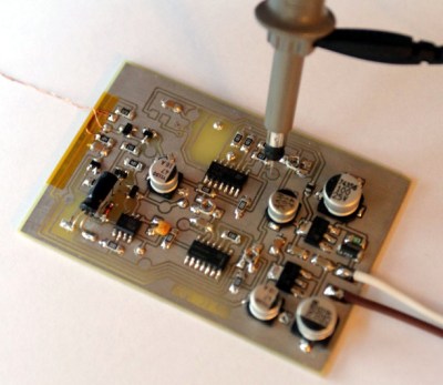
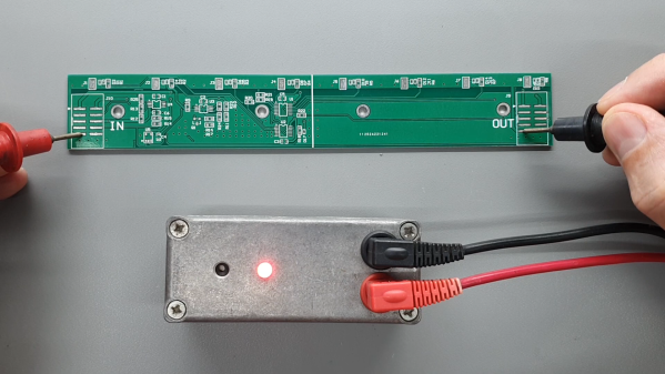
Disgusted by modern commercial testers, [Leo] set out to make the ideal continuity tester in the spirit of old school tools that do one thing and do it really well. It had to be simple to use, always ready to go, and capable of measuring continuity at 5Ω or less resistance (video, embedded below).
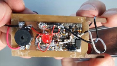
There’s no power switch or even labels, because it doesn’t need any. Just put the probes where you want ’em, and it either beeps and lights the LED or it doesn’t. It looks simple, but inside that blast-resistant enclosure are lots of cool features that certainly make it seem like the ideal tester to us.

Our favorite has to be the transient blocking unit that works like a little circuit breaker. They’re used to protect circuits from lighting and electrostatic discharge by way of depletion-mode MOSFETs and switches to protected mode in under a microsecond. Watch [Leo] build this workbench necessity and then abuse test it with mains power after the break.

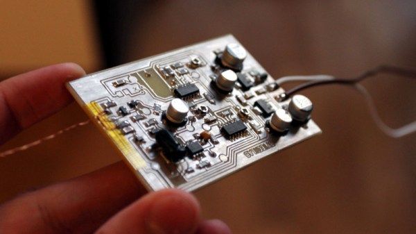
Making your own tools, however simple or complex is a great experience. If you want to up your speedy prototyping game, [Leo]’s got you covered there with a special scratching tool for hand-scribing copper PCBs. Continue reading “Build An Everlasting Continuity Tester”

A Daylight-Readable Bar Graph Display In The 70s Wasn’t Cheap

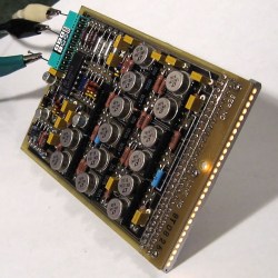
The driver board with display attached; the row of lamps is visible on the right hand side.

LEDs weren’t always an easy solution to displays and indicators. The fine folks at [Industrial Alchemy] shared pictures of a device that shows what kind of effort and cost went into making a high brightness bar graph display in the 70s, back when LEDs were both expensive and not particularly bright. There are no strange materials or methods involved in making the display daylight-readable, but it’s a peek at how solving problems we take for granted today sometimes took a lot of expense and effort.

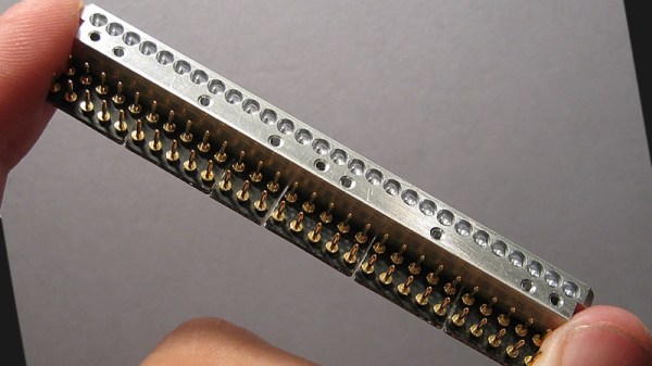
The display is a row of 28 small incandescent bulbs, mounted in a PCB and housed in a machined aluminum frame. Holes through which to view the bulbs are on both the top and front of the metal housing, which allows the unit to be mounted in different orientations. It was made as a swappable module, its 56 machined gold pins mate to sockets on the driver board. The driver board itself consists of 14 LM119 dual comparators, each of which controls two bulbs on the display.

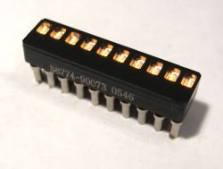
An example of a Wamco minitron bar graph display. Each window contains an incandescent filament. [Source: industrialalchemy.org]
[Industrial Alchemy] believes that the display unit itself may have been a bit of a hack in its own way. Based on the pin spacing and dimensions of the driver board, they feel that it was probably designed to host a row of modular units known as the Wamco minitron bar graph display. An example is pictured here; they resembled DIP chips and could be stacked side-by-side to make a display of any length. Each window contained an incandescent filament in a reflective well, and each light could be individually controlled.

These minitron bar graph units could only be viewed from the top, and were apparently high in cost and low in availability. Getting around these limitations may have been worth creating this compatible unit despite the work involved.

Display technology has taken many different turns over the years, and you can see examples of many of them in one place in the Circus Clock, which tells the time with a different technology for each digit: a nixie, a numitron, a 7-segment thyratron tube, a VFD, an LED dot display, and a rear projection display.

LED “Candle” Gets The 555 Treatment

Regular readers may recall we recently covered a neat Arduino trick that allowed you to “blow out” an LED as if it was a candle. The idea was that the LED itself could be used as a rudimentary temperature sensor, and the Arduino code would turn the LED on and off when a change was detected in its forward voltage drop. You need to oversample the Arduino’s ADC to detect the few millivolt change reliably, but overall it’s pretty simple once you understand the principle.

But [Andrzej Laczewski], like many of our beloved readers, feels the Arduino and other microcontrollers can be a crutch if used exclusively. So he set out to replicate this hack with that most cherished of ICs, the 555 timer. In the video after the break, he demonstrates his “old-school” LED candle for anyone who thinks the only way to control an LED is with digitalWrite.

Not to say it’s easy to replicate the original Arduino project with a 555, or that it’s even practical. [Andrzej] simply wanted to show it was possible, which is something we always respect around these parts. He goes into great detail on how he developed and tested the circuit, even including oscilloscope screenshots showing how the different components work together in real-time. But the short version is that a MOSFET is used to turn the LED on and off, a comparator detects change in the LED’s voltage drop, and the 555 is used to control how long the LED stays off for.

Ever the traditionalist, [Andrzej] wrapped up this build by etching his own PCB using a variation of the classic laser toner transfer method. If this all looks a bit too much like Black Magic to you, there’s no shame in sticking with the Arduino version. At 1/20th of the parts count, and with no calibration required, who’s to say which version is “simpler”.

Continue reading “LED “Candle” Gets The 555 Treatment”

Custom Circuit Makes For Better Battery Level Display

Isn’t it always the way? There’s a circuit right out of the textbooks, or even a chip designed to do exactly what you want — almost exactly. It’s 80% perfect for your application, and rather than accept that 20%, you decide to start from scratch and design your own solution.

That’s the position [Great Scott!] found himself in with this custom LED battery level indicator. As the video below unfolds we learn that he didn’t start exactly from scratch, though. His first pass was the entirely sensible use of the LM3914 10-LED bar graph driver chip, a device that’s been running VU meters and the like for the better part of four decades. With an internal ladder of comparators and 1-kilohm resistors, the chip lights up the 10 LEDs according to an input voltage relative to an upper and lower limit set by external resistors. Unfortunately, the fixed internal resistors make that a linear scale, which does not match the discharge curve of the battery pack he’s monitoring. So, taking design elements from the LM3914 datasheet, [Great Scott!] rolled his own six-LED display from LM324 quad-op amps. Rather than a fixed resistance for each stage, trimmers let him tweak the curve to match the battery, and now he knows the remaining battery life with greater confidence.

Perhaps the 18650 battery pack [Great Scott!] is building is for the e-bike he has been working on lately. If it is, we’re glad to see that he spot-welded the terminals, unlike a recent e-bike battery pack build that may have some problems down the road.

Continue reading “Custom Circuit Makes For Better Battery Level Display”

The Pros And Cons Of Microcontrollers For Boost Converters

It never fails — we post a somewhat simple project using a microcontroller and someone points out that it could have been accomplished better with a 555 timer or discrete transistors or even a couple of vacuum tubes. We welcome the critiques, of course; after all, thoughtful feedback is the point of the comment section. Sometimes the anti-Arduino crowd has a point, but as [Great Scott!] demonstrates with this microcontroller-less boost converter, other times it just makes sense to code your way out of a problem.

Built mainly as a comeback to naysayers on his original boost-converter circuit, which relied on an ATtiny85, [Great Scott!] had to go to considerable lengths to recreate what he did with ease using a microcontroller. He started with a quick demo using a MOSFET driver and a PWM signal from a function generator, which does the job of boosting the voltage, but lacks the feedback needed to control for varying loads.

Ironically relying on a block diagram for a commercial boost controller chip, which is probably the “right” tool for the job he put together the final circuit from a largish handful of components. Two op amps form the oscillator, another is used as a differential amp to monitor the output voltage, and the last one is a used as a comparator to create the PWM signal to control the MOSFET. It works, to be sure, but at the cost of a lot of effort, expense, and perf board real estate. What’s worse, there’s no simple path to adding functionality, like there would be for a microcontroller-based design.

Of course there are circuits where microcontrollers make no sense, but [Great Scott!] makes a good case for boost converters not being one of them if you insist on DIYing. If you’re behind on the basics of DC-DC converters, fear not — we’ve covered that before.

Continue reading “The Pros And Cons Of Microcontrollers For Boost Converters”

How the 555 timer IC works

Learning The 555 From The Inside

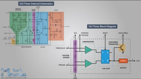
One way to understand how the 555 timer works and how to use it is by learning what the pins mean and what to connect to them. A far more enjoyable, and arguably a more useful way to learn is by looking at what’s going on inside during each of its modes of operation. [Dejan Nedelkovski] has put together just such a video where he walks through how the 555 timer IC works from the inside.

We especially like how he immediately removes the fear factor by first showing a schematic with all the individual components but then grouping them into what they make up: two comparators, a voltage divider, a flip-flop, a discharge transistor, and an output stage. Having lifted the internals to a higher level, he then walks through examples, with external components attached, for each of the three operating modes: bistable, monostable and astable. If you’re already familiar with the 555 then you’ll enjoy the trip down memory lane. If you’re not familiar with it, then you soon will be. Check out his video below.

Continue reading “Learning The 555 From The Inside”

Scrap A Hard Drive, Build A Rotary Encoder

There’s something to be said for the feel of controls. Whether it’s the satisfying snap of a high-quality switch or the buttery touch of the pots on an expensive amplifier, the tactile experience of the controls you interact with says a lot about a device.

[GreatScott!] knows this, and rather than put up with the bump and grind of a cheap rotary encoder, he decided to find an alternative. He ended up exploring hard drive motors as encoders, and while the results aren’t exactly high resolution, he may be onto something. Starting with a teardown of some old HDDs — save those magnets! — [Scott!] found that the motors fell into either the four-lead or three-lead categories. Knowing that HDD motors are brushless DC motors, he reasoned that the four-lead motors had their three windings in Wye configuration with the neutral point brought out to an external connection. A little oscilloscope work showed the expected three-phase output when the motor hub was turned, with the leading and lagging phases changing as the direction of rotation was switched. Hooked to an Arduino, the motor made a workable encoder, later improved by sending each phase through a comparator and using digital inputs rather than using the Nano’s ADCs.

It looks like [GreatScott!]’s current setup only responds to a full rotation of the makeshift encoder, but we’d bet resolution could be improved. Perhaps this previous post on turning BLDC motors into encoders will help.

Continue reading “Scrap A Hard Drive, Build A Rotary Encoder”